Lexus NX: Terminals Of Ecu
TERMINALS OF ECU
CHECK INSTRUMENT PANEL JUNCTION BLOCK ASSEMBLY, MAIN BODY ECU (MULTIPLEX NETWORK BODY ECU)
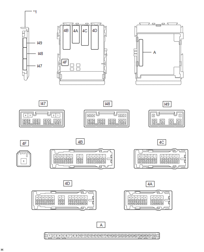
| *1 | Main Body ECU (Multiplex Network Body ECU) | - | - |
(a) Remove the main body ECU (multiplex network body ECU) from the instrument panel junction block assembly.
Click here .gif)
(b) Connect the instrument panel junction block assembly connectors.
(c) Measure the voltage and resistance according to the value(s) in the table below.
| Terminal No. (Symbol) | Wiring Color | Terminal Description | Condition | Specified Condition |
|---|---|---|---|---|
| A-32 (IG) - Body ground | - | Ignition power supply | Power switch on (IG) | 11 to 14 V |
| Power switch off | Below 1 V | |||
| A-31 (BECU) - Body ground | - | Battery power supply | Power switch off | 11 to 14 V |
| A-30 (ACC) - Body ground | - | ACC power supply | Power switch on (ACC) | 11 to 14 V |
| Power switch off | Below 1 V | |||
| A-11 (GND1) - Body ground | - | Ground | Always | Below 1 Ω |
If the result is not as specified, there may be a malfunction in the wire harness or instrument panel junction block assembly.
(d) Install the main body ECU (multiplex network body ECU).
Click here
(e) Measure the voltage and pulse according to the value(s) in the table below.
| Terminal No. (Symbol) | Wiring Color | Terminal Description | Condition | Specified Condition |
|---|---|---|---|---|
| I48-6 (FLCY) - Body ground | G - Body ground | Front door courtesy light switch LH signal | Front door LH open | Below 1 V |
| Front door LH closed | Pulse generation | |||
| I48-27 (FRCY) - Body ground | W - Body ground | Front door courtesy light switch RH signal | Front door RH open | Below 1 V |
| Front door RH closed | Pulse generation | |||
| I47-2 (LSWR) - Body ground | Y - Body ground | Rear door unlock detection switch RH signal | Rear door RH unlocked | Below 1 V |
| Power switch off, all doors closed and rear door RH locked | Pulse generation | |||
| 4D-39 (LSFR) - Body ground | P - Body ground | Front door unlock detection switch RH signal | Front door RH unlocked | Below 1 V |
| Power switch off, all doors closed and front door RH locked | Pulse generation | |||
| 4D-37 (RCTY) - Body ground | Y - Body ground | Rear door courtesy light switch RH signal | Rear door RH open | Below 1 V |
| Rear door RH closed | Pulse generation | |||
| 4A-34 (LSWL) - Body ground | Y - Body ground | Rear door unlock detection switch LH signal | Rear door LH unlocked | Below 1 V |
| Power switch off, all doors closed and rear door LH locked | Pulse generation | |||
| 4A-21 (BCTY) - Body ground | R - Body ground (w/o Rear Power Seat System) LG - Body ground (w/ Rear Power Seat System) | Back door courtesy light switch signal | Back door open | Below 1 V |
| Back door closed | 11 to 14 V | |||
| 4A-18 (LCTY) - Body ground | W - Body ground | Rear door courtesy light switch LH signal | Rear door LH open | Below 1 V |
| Rear door LH closed | Pulse generation | |||
| 4D-40 (LSFL) - Body ground | B - Body ground | Front door unlock detection switch LH signal | Front door LH unlocked | Below 1 V |
| Power switch off, all doors closed and front door LH locked | Pulse generation | |||
| 4C-46 (DOMR) - Body ground | R - Body ground | Battery saving control (interior light auto cut function) signal | Battery saving control (interior light auto cut function) operating | Below 1 V |
| Battery saving control (interior light auto cut function) not operating | 11 to 14 V | |||
| 4C-39 - Body ground | B - Body ground | Headlight dimmer switch tail signal | Headlight dimmer switch in tail position | Below 1 V |
| Headlight dimmer switch not in tail position | 11 to 14 V | |||
| 4D-36 (ILE) - Body ground | SB - Body ground | Map light and spot light signal | Map light and spot light on using illuminated entry system | Below 1 V |
| Map light and spot light off using illuminated entry system | 11 to 14 V | |||
| 4D-32 (FSPT) - Body ground | W - Body ground | Interior illumination light LH signal | Interior illumination LH light on | Below 1 V |
| Interior illumination LH light off | 11 to 14 V | |||
| 4D-33 (FSPT) - Body ground | B - Body ground | Interior illumination light RH signal | Interior illumination RH light on | Below 1 V |
| Interior illumination RH light off | 11 to 14 V | |||
| I47-4 (MILE) - Body ground | P - Body ground | Door outside handle illumination light signal | Door outside handle illumination light on | 11 to 14 V |
| Door outside handle illumination light off | Below 1 V | |||
| I47-27 (DMDR) - Body ground | W - Body ground | Map light door switch signal input | Map light door switch on | Below 1 V |
| Map light door switch off | 11 to 14 V | |||
| I47-28 (DMON) - Body ground | B - Body ground | Map light front dome light switch signal input | Map light front dome light switch on | Below 1 V |
| Map light front dome light switch off | Pulse generation |
CHECK CERTIFICATION ECU (SMART KEY ECU ASSEMBLY)
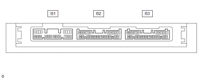
(a) Disconnect the I53 certification ECU connector.
(b) Measure the voltage and resistance according to the value(s) in the table below.
| Terminal No. (Symbol) | Wiring Color | Terminal Description | Condition | Specified Condition |
|---|---|---|---|---|
| I53-10 (+B) - Body ground | W - Body ground | Battery power supply | Power switch off | 11 to 14 V |
| I53-11 (E) - Body ground | W-B - Body ground | Ground | Always | Below 1 Ω |
If the result is not as specified, there may be a malfunction on the wire harness side.
(c) Reconnect the I53 certification ECU connector.
(d) Measure the voltage according to the value(s) in the table below.
| Terminal No. (Symbol) | Wiring Color | Terminal Description | Condition | Specified Condition |
|---|---|---|---|---|
| I53-17 (SWIL) - I53-12 (AGND) | BE - P | Power switch illumination operation signal | Power switch illumination on | 11 to 14 V |
| Power switch illumination off | Below 1 V |
READ NEXT:
 Data List / Active Test
DATA LIST / ACTIVE TEST DATA LIST NOTICE: In the table below, the values listed under "Normal Condition" are reference values. Do not depend solely on these reference values when deciding whether a pa
IG Signal Circuit
DESCRIPTION This circuit detects whether the power switch is on (IG) or off, and sends this information to the main body ECU (multiplex network body ECU). WIRING DIAGRAM CAUTION / NOTICE / HINT NOTI
ACC Signal Circuit
DESCRIPTION This circuit detects whether the power switch is on (ACC) or off, and sends this information to the main body ECU (multiplex network body ECU). WIRING DIAGRAM CAUTION / NOTICE / HINT NOT
SEE MORE:
Vehicle Speed Sensor Malfunction (B2415)
DESCRIPTION The headlight ECU sub-assembly LH receives speed signals from the brake booster with master cylinder assembly (skid control ECU) via CAN communication and performs light control. DTC No. Detection Item DTC Detection Condition Trouble Area B2415 Vehicle Speed Sensor Malfunc
Relay
On-vehicle InspectionON-VEHICLE INSPECTION PROCEDURE 1. INSPECT HORN RELAY ASSEMBLY (a) Remove the horn relay assembly. (b) Measure the resistance according to the value(s) in the table below. Standard Resistance: Tester Connection Condition Specified Condition 3 - 5 Vo
