Lexus NX: IG Signal Circuit
DESCRIPTION
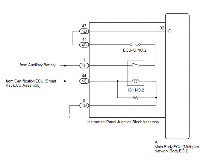
This circuit detects whether the power switch is on (IG) or off, and sends this information to the main body ECU (multiplex network body ECU).
WIRING DIAGRAM
CAUTION / NOTICE / HINT
NOTICE:
- Inspect the fuses for circuits related to this system before performing the following procedure.
- Recognition code registration is necessary when replacing the main body ECU (multiplex network body ECU).
- If the main body ECU (multiplex network body ECU) is replaced, refer to Registration.
PROCEDURE
| 1. | READ VALUE USING TECHSTREAM (IG SW) |
(a) Using the Techstream, read the Data List.
Click here .gif)
| Tester Display | Measurement Item | Range | Normal Condition | Diagnostic Note |
|---|---|---|---|---|
| IG SW | Power switch on (IG) signal | ON or OFF | ON: Power switch on (IG) OFF: Power switch off | "OFF" is also displayed for this item when the power switch is on (ACC). |
| Tester Display |
|---|
| IG SW |
OK:
The display is as specified in the normal condition column.
| OK | .gif) | PROCEED TO NEXT SUSPECTED AREA SHOWN IN PROBLEM SYMPTOMS TABLE |
|
.gif)
| 2. | CHECK HARNESS AND CONNECTOR (INSTRUMENT PANEL JUNCTION BLOCK ASSEMBLY - BATTERY AND BODY GROUND) |
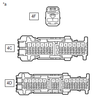
| (a) Disconnect the instrument panel junction block assembly connectors. |
|
(b) Measure the voltage according to the value(s) in the table below.
Standard Voltage:
| Tester Connection | Switch Condition | Specified Condition |
|---|---|---|
| 4F-1 - Body ground | Power switch off | 11 to 14 V |
| 4C-44 - Body ground | Power switch on (IG) | 11 to 14 V |
(c) Measure the resistance according to the value(s) in the table below.
Standard Resistance:
| Tester Connection | Condition | Specified Condition |
|---|---|---|
| 4D-9 - Body ground | Always | Below 1 Ω |
| NG | | REPAIR OR REPLACE HARNESS OR CONNECTOR |
|
| 3. | CHECK HARNESS AND CONNECTOR (INSTRUMENT PANEL JUNCTION BLOCK ASSEMBLY CIRCUIT) |
(a) Disconnect the 4C and 4D instrument panel junction block assembly connectors.
(b) Measure the resistance according to the value(s) in the table below.
Standard Resistance:
| Tester Connection | Condition | Specified Condition |
|---|---|---|
| 4C-41 - 4D-43 | Always | Below 1 Ω |
| 4C-41 or 4D-43 - Body ground | Always | 10 kΩ or higher |
| NG | | REPAIR OR REPLACE HARNESS OR CONNECTOR |
|
| 4. | INSPECT INSTRUMENT PANEL JUNCTION BLOCK ASSEMBLY |
| (a) Remove the instrument panel junction block assembly. Click here |
|
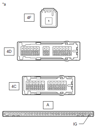
(b) Remove the main body ECU (multiplex network body ECU) from the instrument panel junction block assembly.
Click here
(c) Measure the resistance according to the value(s) in the table below.
Standard Resistance:
| Tester Connection | Condition | Specified Condition |
|---|---|---|
| A-32 (IG) - 4D-43 | Always | Below 1 Ω |
| 4F-1 - 4C-41 | Not connected | 10 kΩ or higher |
| 4F-1 - 4C-41 | Battery positive (+) → 4C-44 Battery negative (-) → 4D-9 | Below 1 Ω |
| OK | | REPLACE MAIN BODY ECU (MULTIPLEX NETWORK BODY ECU) |
| NG | | REPLACE INSTRUMENT PANEL JUNCTION BLOCK ASSEMBLY |
READ NEXT:
 ACC Signal Circuit
DESCRIPTION This circuit detects whether the power switch is on (ACC) or off, and sends this information to the main body ECU (multiplex network body ECU). WIRING DIAGRAM CAUTION / NOTICE / HINT NOT
Door Courtesy Switch Circuit
DESCRIPTION The main body ECU (multiplex network body ECU) receives a door open or closed signal from each door courtesy light switch. WIRING DIAGRAM CAUTION / NOTICE / HINT NOTICE:
Recognition co
Back Door Courtesy Switch Circuit
DESCRIPTION The main body ECU (multiplex network body ECU) receives a back door open or closed signal from the back door courtesy light switch. WIRING DIAGRAM CAUTION / NOTICE / HINT NOTICE:
Recog
SEE MORE:
Confirm Vehicle Headunit Functionality
PROCEDURE 1. CHECK PROBLEM SYMPTOMS (a) Check the app type when the problem occurred. Result Proceed to When using Fleet Apps A When using Infotainment App B B GO TO STEP 3
A 2. CONFIRM THE LEXUS APP SUITE APP [FLEET APP] IS DOWNLOADED T
Removal
REMOVAL PROCEDURE 1. PRECAUTION NOTICE: After turning the power switch is turned off, there may be a waiting time before disconnecting the auxiliary negative (-) battery terminal. Click here 2. CUSTOMIZE POWER TILT AND POWER TELESCOPIC STEERING COLUMN SYSTEM (a) Disable the auto tilt away function
