Lexus NX: P/W Master Switch Communication Stop (B1206)
DESCRIPTION
This DTC is stored when LIN communication between the multiplex network master switch assembly and main body ECU (multiplex network body ECU) stops for 10 seconds or more.
| DTC No. | Detection Item | DTC Detection Condition | Trouble Area |
|---|---|---|---|
| B1206 | P/W Master Switch Communication Stop | No communication between multiplex network master switch assembly and main body ECU (multiplex network body ECU) for 10 seconds or more. |
|
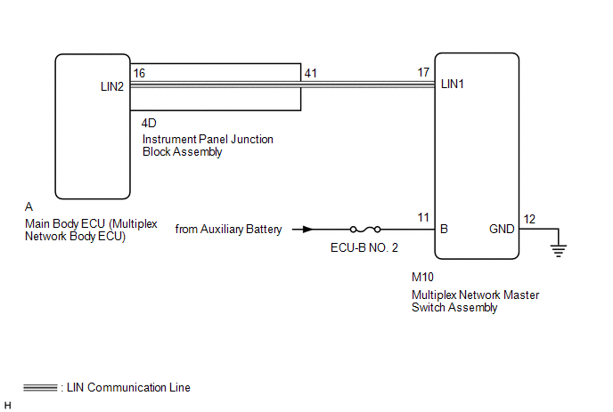
WIRING DIAGRAM
CAUTION / NOTICE / HINT
NOTICE:
-
When using the Techstream with the power switch off to troubleshoot:
Connect the Techstream to the vehicle, and turn a courtesy switch on and off at 1.5 second intervals until communication between the Techstream and vehicle begins.
- Inspect the fuses for circuits related to this system before performing the following procedure.
- Recognition code registration is necessary when replacing the main body ECU (multiplex network body ECU).
-
If the main body ECU (multiplex network body ECU) is replaced, refer to Registration.
Click here
.gif)
HINT:
DTC B2325 is output when the communication between all of the following components and main body ECU (multiplex network body ECU) stops.
Click here
PROCEDURE
| 1. | CLEAR DTC |
(a) Clear the DTCs.
Click here
|
.gif)
| 2. | CHECK FOR DTC |
(a) Check for DTCs.
Click here
| DTC B1206 is not output | .gif) | USE SIMULATION METHOD TO CHECK |
|
| 3. | CHECK HARNESS AND CONNECTOR (MAIN BODY ECU [MULTIPLEX NETWORK BODY ECU] - MULTIPLEX NETWORK MASTER SWITCH ASSEMBLY) |
(a) Remove the main body ECU (multiplex network body ECU) from the instrument panel junction block assembly.
Click here
(b) Disconnect the M10 multiplex network master switch assembly connector.
(c) Measure the resistance according to the value(s) in the table below.
Standard Resistance:
| Tester Connection | Condition | Specified Condition |
|---|---|---|
| A-16 (LIN2) - M10-17 (LIN1) | Always | Below 1 Ω |
| A-16 (LIN2) - Body ground | Always | 10 kΩ or higher |
| NG | | GO TO STEP 7 |
|
| 4. | CHECK HARNESS AND CONNECTOR (MULTIPLEX NETWORK MASTER SWITCH ASSEMBLY - BATTERY AND BODY GROUND) |
| (a) Disconnect the multiplex network master switch assembly connector. |
|
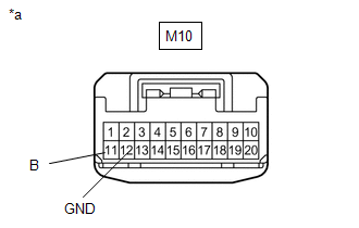
(b) Measure the resistance according to the value(s) in the table below.
Standard Resistance:
| Tester Connection | Condition | Specified Condition |
|---|---|---|
| M10-12 (GND) - Body ground | Always | Below 1 Ω |
(c) Measure the voltage according to the value(s) in the table below.
Standard Voltage:
| Tester Connection | Switch Condition | Specified Condition |
|---|---|---|
| M10-11 (B) - Body ground | Power switch off | 11 to 14 V |
| NG | | REPAIR OR REPLACE HARNESS OR CONNECTOR |
|
| 5. | REPLACE MULTIPLEX NETWORK MASTER SWITCH ASSEMBLY |
(a) Temporarily replace the multiplex network master switch assembly with a new or normally functioning one.
Click here
(b) Clear the DTCs.
Click here
|
| 6. | CHECK FOR DTC |
(a) Check for DTCs.
Click here
| DTC B1206 is not output | | END (MULTIPLEX NETWORK MASTER SWITCH ASSEMBLY IS DEFECTIVE) |
| DTC B1206 is output | | REPLACE MAIN BODY ECU (MULTIPLEX NETWORK BODY ECU) |
| 7. | CHECK HARNESS AND CONNECTOR (INSTRUMENT PANEL JUNCTION BLOCK ASSEMBLY - MULTIPLEX NETWORK MASTER SWITCH ASSEMBLY) |
(a) Remove the main body ECU (multiplex network body ECU) from the instrument panel junction block assembly.
Click here
(b) Disconnect the M10 multiplex network master switch assembly connector.
(c) Measure the resistance according to the value(s) in the table below.
Standard Resistance:
| Tester Connection | Condition | Specified Condition |
|---|---|---|
| 4D-41 - M10-17 (LIN1) | Always | Below 1 Ω |
| 4D-41 - Body ground | Always | 10 kΩ or higher |
| OK | | REPLACE INSTRUMENT PANEL JUNCTION BLOCK ASSEMBLY |
| NG | | REPAIR OR REPLACE HARNESS OR CONNECTOR |
READ NEXT:
 Sliding Roof ECU Communication Stop (B1273)
DESCRIPTION This DTC is stored when LIN communication between the sliding roof drive gear sub-assembly and main body ECU (multiplex network body ECU) stops for 10 seconds or more. DTC No. Detecti
Driver Side Door ECU Communication Stop (B2321)
DESCRIPTION This DTC is stored when LIN communication between the front power window regulator motor assembly LH and main body ECU (multiplex network body ECU) stops for 10 seconds or more. DTC No.
Front Passenger Side Door ECU Communication Stop (B2322)
DESCRIPTION This DTC is output when LIN communication between the front power window regulator motor assembly RH and main body ECU (multiplex network body ECU) stops for 10 seconds or more. DTC No.
SEE MORE:
Inspection
INSPECTION PROCEDURE 1. INSPECT HEADUP DISPLAY SWITCH ASSEMBLY *1 HUD Switch *2 TILT Switch *3 RHEOSTAT Switch *4 DISP Switch *a Component without harness connected (Headup Display Switch Assembly) (a) Check the resistance. Measure the resistance according to the val
Data List / Active Test
DATA LIST / ACTIVE TEST DATA LIST HINT: Using the Techstream to read the Data List allows the values or states of switches, sensors, actuators and other items to be read without removing any parts. This non-intrusive inspection can be very useful because intermittent conditions or signals may be dis
