Lexus NX: Terminals Of Ecu
TERMINALS OF ECU
| Terminal No. (Symbol) | Wiring Color | Terminal Description | Condition | Specified Condition |
|---|---|---|---|---|
|
*1: w/ Manual (SOS) Switch
*2: It is connected, but not used *3: w/o Manual (SOS) Switch #: There is no wire color information | ||||
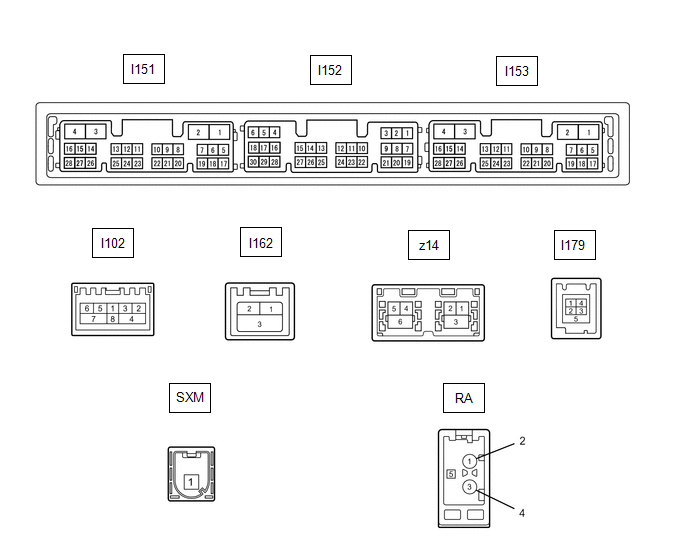
| I151-1 (GND1) - Body ground | W-B - Body ground | Ground | Always | Below 1 Ω |
| I151-2 (GND2) - Body ground | B - Body ground | Ground | Always | Below 1 Ω |
| I151-3 (+B) - I151-1 (GND1) | R - W-B | Power source (+B) | Power switch off | 11 to 14 V |
| I151-4 (+B1) - I151-1 (GND1) | B - W-B | Power source (+B) | Power switch off | 11 to 14 V |
| I151-5 (TX1+) | B | AVC-LAN communication signal | - | - |
| I151-6 (TX1-) | P | AVC-LAN communication signal | - | - |
| I151-10 (AGND) - I151-1 (GND1) | Shielded - W-B | Shield ground | Always | Below 1 Ω |
| I151-11 (VAL+) - I151-13 (VA-) | B - R | Sound signal (Left) | External device system playing (when No. 1 stereo jack adapter assembly used) | A waveform synchronized with sound signals is output |
| I151-12 (VAR+) - I151-13 (VA-) | W - R | Sound signal (Right) | External device system playing (when No. 1 stereo jack adapter assembly used) | A waveform synchronized with sound signals is output |
| I151-13 (VA-) - I151-1 (GND1) | R - W-B | Sound signal ground | Always | Below 1 Ω |
| I151-14 (ADPG) - I151-13 (VA-) | L - R | External device connection detection signal | External device connected | 1.3 to 1.8 V |
| External device not connected | 2.2 to 3.3 V | |||
| I151-15 (ACC1) - I151-1 (GND1) | GR - W-B | Power source (ACC) | Power switch on (ACC) | 11 to 14 V |
| Power switch off | Below 1 V | |||
| I151-16 (ACC) - I151-1 (GND1) | Y - W-B | Power source (ACC) | Power switch on (ACC) | 11 to 14 V |
| Power switch off | Below 1 V | |||
| I151-21 (SW1) - I151-24 (SWG) | P - BR | Steering pad switch signal | No switch pushed | 2.97 to 3.56 V |
| Seek+ switch pushed | 0.27 to 0.35 V | |||
| Seek- switch pushed | 0.86 to 1.03 V | |||
| Vol+ switch pushed | 1.51 to 1.79 V | |||
| Vol- switch pushed | 2.22 to 2.66 V | |||
| I151-22 (SW2) - I151-24 (SWG) | R - BR | Steering pad switch signal | No switch pushed | 2.97 to 3.56 V |
| MODE switch pushed | 0.27 to 0.35 V | |||
| On hook switch pushed | 0.86 to 1.03 V | |||
| Off hook switch pushed | 1.51 to 1.79 V | |||
| Voice switch pushed | 2.22 to 2.66 V | |||
| I151-24 (SWG) - Body ground | BR - Body ground | Steering pad switch signal | Always | Below 1 Ω |
| I151-27 (SPD) - I151-1 (GND1) | W - W-B | Vehicle speed signal | See "Vehicle Signal Check Mode" in Operation Check | - |
| I153-7 (SUP) - I151-1 (GND1) | B - W-B | Start up signal | 20 seconds elapse after turning the power switch on (ACC) | 11 to 14 V |
| I153-10 (USBV) - I151-1 (GND1)*1 | G - W-B | DCM (telematics transceiver) power supply | Power switch off | Below 1 V |
| Power switch on (ACC) | 4.75 to 5.25 V | |||
| I153-11 (USBG) - Body ground*1 | P - Body ground | Ground | Always | Below 1 Ω |
| I153-12 (SGND) - Body ground*1 | Shielded - Body ground | Shield ground | Always | Below 1 Ω |
| I153-13 (VOR+) - I151-1 (GND1)*1 | R - W-B | Receive voice signal | Destination assist service in use and operator speaking to vehicle occupant | A waveform synchronized with the received voice is output. |
| I153-14 (VOR-) - I151-1 (GND1)*1 | G - W-B | Receive voice signal | Destination assist service in use and operator speaking to vehicle occupant | A waveform synchronized with the received voice is output. |
| I153-15 (VOT+) - I151-1 (GND1)*1 | B - W-B | Sent voice signal | Destination assist service in use and vehicle occupant speaking to operator | A waveform synchronized with the sent voice is output. |
| I153-16 (VOT-) - I151-1 (GND1)*1 | W - W-B | Sent voice signal | Destination assist service in use and vehicle occupant speaking to operator | A waveform synchronized with the sent voice is output. |
| I153-19 (RST)*2 | Y | - | - | - |
| I153-22 (SI+) - I151-1 (GND1) | B - W-B | Voice signal | Voice guidance sounding | A waveform synchronized with sound is output |
| I153-23 (SI-) - I151-1 (GND1) | W - W-B | Voice signal | Voice guidance sounding | A waveform synchronized with sound is output |
| I153-24 (SGND) - I151-1 (GND1) | Shielded - W-B | Shield ground | Always | Below 1 Ω |
| I153-25 (MCO+) - I153-26 (MCO-) | B - W | Microphone voice signal | See "Check Microphone (DCU)" in Operation Check | - |
| I153-26 (MCO-) - I151-1 (GND1) | W - W-B | Microphone voice signal | See "Check Microphone (DCU)" in Operation Check | - |
| I153-28 (REV2) - I151-1 (GND1) | R - W-B | Reverse signal | Power switch on (READY), shift position not in R → in R | 2 V or less → 11 to 14 V |
| I152-1 (VMTF) - I151-1 (GND1) | V - W-B | Visual mute signal | Power switch on (ACC) Screen display changing | 3.5 V or higher → Below 1 V → 3.5 V or higher |
| I152-5 (CNH1) | L | Local bus communication signal | - | - |
| I152-6 (CNL1) | W | Local bus communication signal | - | - |
| I152-13 (CANH) | B | CAN communication signal | - | - |
| I152-14 (CANL) | W | CAN communication signal | - | - |
| I152-15 (ILL+) - I151-1 (GND1) | L - W-B | Illumination signal | Power switch on (IG), Light control switch in tail or head position | Below 1 V → 11 to 14 V |
| I152-16 (ILL-) - I151-1 (GND1) | V - W-B | Illumination signal | Power switch on (IG), light control switch off → tail or head position (Light intensity is not max or min.) | Below 1 V → Pulse generation |
| I152-19 (IG) - I151-1 (GND1) | P - W-B | Power source (IG) | Power switch off | Below 1 V |
| Power switch on (IG) | 11 to 14 V | |||
| I152-21 (MIN+) - I151-1 (GND1) | W - W-B | Microphone voice signal | See "Check Microphone" in Operation Check | - |
| I152-22 (MIN-) - I151-1 (GND1) | R - W-B | Microphone voice signal | See "Check Microphone" in Operation Check | - |
| I152-23 (MACC) - I151-1 (GND1)*3 | B - W-B | Telephone microphone assembly power supply | Power switch off | Below 1 V |
| Power switch on (ACC) | 4 to 6 V | |||
| I152-24 (SGND) - Body ground | Shielded - Body ground | Shield ground | Always | Below 1 Ω |
| I152-25 (SNS2) - I151-1 (GND1) | P - W-B | Microphone connection detection signal | Always | Below 1 V |
| I102-1 (WUO) | W | MOST communication signal | Power switch on (ACC) | 4.5 V or higher |
| Power switch off | Below 1 V | |||
| I102-2 (MI+) | B | MOST communication signal | - | - |
| I102-3 (MI-) | B | MOST communication signal | - | - |
| I102-4 (SLDI) - I151-1 (GND1) | Shielded - W-B | Shield ground | Always | Below 1 Ω |
| I102-5 (MO+) | B | MOST communication signal | - | - |
| I102-6 (MO-) | B | MOST communication signal | - | - |
| I102-7 (SLDO) - I151-1 (GND1) | Shielded - W-B | Shield ground | Always | Below 1 Ω |
| I162-1 (GVI-) | # | Video signal (Digital) | - | - |
| I162-2 (GVI+) | # | Video signal (Digital) | - | - |
| I162-3 (GVG1) - Body ground | Shielded - Body ground | Shield ground | Always | Below 1 Ω |
| I179-1 (USV1) | # | Power source | - | - |
| I179-2 (US1-) | # | Data signal | - | - |
| I179-3 (US1+) | # | Data signal | - | - |
| I179-4 (UGD1) | # | Ground | - | - |
| I179-5 (USG1) - Body ground | Shielded - Body ground | Shield ground | Always | Below 1 Ω |
| z14-1 (GV2-) | # | Video signal (Digital) | - | - |
| z14-2 (GV2+) | # | Video signal (Digital) | - | - |
| z14-3 (GVG2) - Body ground | Shielded - Body ground | Shield ground | Always | Below 1 Ω |
| z14-4 (US4+) | # | USB communication line | - | - |
| z14-5 (US4-) | # | USB communication line | - | - |
| z14-6 (UGD4) - Body ground | Shielded - Body ground | Shield ground | Always | Below 1 Ω |
| RA-5 - I151-1 (GND1) | # - W-B | Power source of antenna | Power switch on (ACC) Radio switch on and AM or FM selected | 11 to 14 V |
RADIO RECEIVER ASSEMBLY
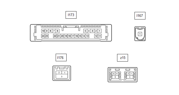
NAVIGATION ECU
| Terminal No. (Symbol) | Wiring Color | Terminal Description | Condition | Specified Condition |
|---|---|---|---|---|
|
*1: It is connected, but not used
*2: w/ Manual (SOS) Switch | ||||
| I173-6 (VOI+) - I173-23 (GND) | B - W-B | Voice signal | Voice guidance sounding | A waveform synchronized with sound is output |
| I173-7 (VOI-) - I173-23 (GND) | W - W-B | Voice signal | Voice guidance sounding | A waveform synchronized with sound is output |
| I173-8 (SLD1) - Body ground | Shielded - Body ground | Shield ground | Always | Below 1 Ω |
| I173-9 (SPD) - I173-23 (GND) | V - W-B | Vehicle speed signal | See "Check GPS and Vehicle Sensors" in Operation Check | - |
| I173-10 (+B) - I173-23 (GND) | R - W-B | Power source (+B) | Power switch off | 11 to 14 V |
| I173-13 (MIC+) - I173-23 (GND) | B - W-B | Microphone voice signal | See "Microphone Check (MEU)" in Operation Check | - |
| I173-14 (MIC-) - Body ground | W - Body ground | Microphone voice signal | See "Microphone Check (MEU)" in Operation Check | - |
| I173-19 (REV2) - I173-23(GND) | R - W-B | Reverse signal | Power switch on (READY), shift position not in R → in R | 2 V or less → 11 to 14 V |
| I173-21 (SUP) - I173-23 (GND) | B - W-B | Power source (ACC) | 20 seconds elapse after turning the power switch on (ACC) | 11 to 14 V |
| I173-22 (RST)*1 | Y | - | - | - |
| I173-23 (GND) - Body ground | W-B - Body ground | Ground | Always | Below 1 Ω |
| I176-1 (USB+)*2 | # | USB communication line | - | - |
| I176-2 (USB-)*2 | # | USB communication line | - | - |
| I176-3 (USBS) - Body ground*2 | Shielded - Body ground | Shield ground | Always | Below 1 Ω |
| z15-1 (GVO-) | # | Video signal (Digital) | - | - |
| z15-2 (GVO+) | # | Video signal (Digital) | - | - |
| z15-3 (GVG1) - Body ground | Shielded - Body ground | Shield ground | Always | Below 1 Ω |
| z15-4 (US4+) | # | USB communication line | - | - |
| z15-5 (US4-) | # | USB communication line | - | - |
| z15-6 (UGD4) - Body ground | Shielded - Body ground | Shield ground | Always | Below 1 Ω |
| I167-1 (GPS) | # | GPS signal | - | - |
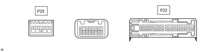
STEREO COMPONENT AMPLIFIER ASSEMBLY
| Terminal No. (Symbol) | Wiring Color | Terminal Description | Condition | Specified Condition |
|---|---|---|---|---|
|
*1: for 14 Speakers
*2: w/ Manual (SOS) Switch #: There is no wire color information | ||||
| P22-1 (+B) - Body ground*1 | R - Body ground | Power source (+B) | Power switch off | 11 to 14 V |
| P22-2 (TMUT) - Body ground*2 | B - Body ground | Mute signal | Audio system playing | 3.0 to 5.0 V |
| Emergency call mode | Below 1 V | |||
| P22-3 (GND) - Body ground | W-B - Body ground | Ground | Always | Below 1 Ω |
| P22-4 (WFL+) - P22-3 (GND) | B - W-B | Sound signal (Front Left) | Audio system playing | A waveform synchronized with sound signals is output |
| P22-5 (WFR+) - P22-3 (GND) | W - W-B | Sound signal (Front Right) | Audio system playing | A waveform synchronized with sound signals is output |
| P22-6 (WF1+) - P22-3 (GND) | B - W-B | Sound signal (Woofer) | Audio system playing | A waveform synchronized with sound signals is output |
| P22-7 (CTR+) - P22-3 (GND) | P - W-B | Sound signal (Front Center) | Audio system playing | A waveform synchronized with sound signals is output |
| P22-8 (RL+) - P22-3 (GND) | R - W-B | Sound signal (Rear Left) | Audio system playing | A waveform synchronized with sound signals is output |
| P22-9 (RR+) - P22-3 (GND) | B - W-B | Sound signal (Rear Right) | Audio system playing | A waveform synchronized with sound signals is output |
| P22-10 (SL+) - P22-3 (GND)*1 | LG - W-B | Sound signal (Rear Left) | Audio system playing | A waveform synchronized with sound signals is output |
| P22-11 (SR+) - P22-3 (GND)*1 | R - W-B | Sound signal (Rear Right) | Audio system playing | A waveform synchronized with sound signals is output |
| P22-12 (FL+) - P22-3 (GND) | P - W-B | Sound signal (Front Left) | Audio system playing | A waveform synchronized with sound signals is output |
| P22-13 (FR+) - P22-3 (GND) | P - W-B | Sound signal (Front Right) | Audio system playing | A waveform synchronized with sound signals is output |
| P22-16 (+B2) - P22-3 (GND) | B - W-B | Power source (+B) | Power switch off | 11 to 14 V |
| P22-17 (SPD) - P22-3 (GND) | V - W-B | Vehicle speed signal | Power switch on (IG) Wheel being rotated | Pulse generation |
| P22-18 (GND2) - Body ground | W-B - Body ground | Ground | Always | Below 1 Ω |
| P22-19 (WFL-) - P22-3 (GND) | Y - W-B | Sound signal (Front Left) | Audio system playing | A waveform synchronized with sound signals is output |
| P22-20 (WFR-) - P22-3 (GND) | R - W-B | Sound signal (Front Right) | Audio system playing | A waveform synchronized with sound signals is output |
| P22-21 (WF1-) - P22-3 (GND) | G - W-B | Sound signal (Woofer) | Audio system playing | A waveform synchronized with sound signals is output |
| P22-22 (CTR-) - P22-3 (GND) | R - W-B | Sound signal (Front Center) | Audio system playing | A waveform synchronized with sound signals is output |
| P22-23 (RL-) - P22-3 (GND) | W - W-B | Sound signal (Rear Left) | Audio system playing | A waveform synchronized with sound signals is output |
| P22-24 (RR-) - P22-3 (GND) | G - W-B | Sound signal (Rear Right) | Audio system playing | A waveform synchronized with sound signals is output |
| P22-25 (SL-) - P22-3 (GND)*1 | L - W-B | Sound signal (Rear Left) | Audio system playing | A waveform synchronized with sound signals is output |
| P22-26 (SR-) - P22-3 (GND)*1 | P - W-B | Sound signal (Rear Right) | Audio system playing | A waveform synchronized with sound signals is output |
| P22-27 (FL-) - P22-3 (GND) | V - W-B | Sound signal (Front Left) | Audio system playing | A waveform synchronized with sound signals is output |
| P22-28 (FR-) - P22-3 (GND) | R - W-B | Sound signal (Front Right) | Audio system playing | A waveform synchronized with sound signals is output |
| P29-2 (MI+) | B | MOST communication signal | - | - |
| P29-3 (MI-) | B | MOST communication signal | - | - |
| P29-4 (SLDI) | Shielded | Shield ground | - | - |
| P29-5 (MO+) | B | MOST communication signal | - | - |
| P29-6 (MO-) | B | MOST communication signal | - | - |
| P29-7 (SLDO) | Shielded | Shield ground | - | - |
| P29-8 (WUI) | W | MOST communication wake-up signal | - | - |
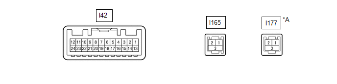
MULTI-DISPLAY ASSEMBLY
| *A | w/ Panoramic View Monitor System | - | - |
| Terminal No. (Symbol) | Wiring Color | Terminal Description | Condition | Specified Condition |
|---|---|---|---|---|
|
*1: w/ Panoramic View Monitor System
*2: w/ Parking Assist Monitor System and w/o Intuitive Parking Assist System *3: w/ Parking Assist Monitor System *4: w/ Parking Assist Monitor System and w/ Intuitive Parking Assist System #: There is no wire color information | ||||
| I42-1 (CSW+) - I42-13 (GND1)*1 | P - W-B | Camera image change signal (GVIF) | Power switch on (READY), shift position not in R → in R | 3.5 V or higher → Below 1 V |
| I42-2 (ILL) - I42-13 (GND1) | LG - W-B | Illumination signal | Power switch on (IG), light control switch off → tail or head position | Below 1 V → 11 to 14 V |
| I42-3 (REV) - I42-13(GND1)*2 | R - W-B | Reverse signal | Power switch on (READY), shift position not in R → in R | 2 V or less → 11 to 14 V |
| I42-7 (TX+) | B | AVC-LAN communication signal | - | - |
| I42-8 (V+) - I42-9 (V-)*3 | W - R | Video signal | Power switch on (READY) Shift position in R Camera lens not covered, displaying image | Pulse generation (Refer to waveform 1) |
| Power switch on (READY) Shift position in R Camera lens covered, blacking out screen | Pulse generation (Refer to waveform 2) | |||
| I42-9 (V-) - Body ground*3 | R - Body ground | Video signal ground | Always | Below 1 Ω |
| I42-10 (CA+) - I42-21 (CGND)*3 | B - G | Power source | Power switch on (ACC) | 5.5 to 7.05 V |
| I42-11 (VMTI) - I42-13 (GND1) | V - W-B | Visual mute signal | When image on display switches | 3.5 V or higher → Below 1 V → 3.5 V or higher |
| I42-12 (B) - I42-13 (GND1) | BE - W-B | Power source (+B) | Power switch off | 11 to 14 V |
| I42-13 (GND1) - Body ground | W-B - Body ground | Ground | Always | Below 1 Ω |
| I42-14 (CSWA) - I42-13(GND1)*4 | V - W-B | Camera image change signal | Power switch on (READY) Intuitive parking assist image not being displayed → intuitive parking assist image being displayed | 3.5 V or higher → Below 1 V |
| I42-19 (TX-) | P | AVC-LAN communication signal | - | - |
| I42-20 (CSLD) - Body ground*3 | Shielded - Body ground | Shield ground | Always | Below 1 Ω |
| I42-21 (CGND) - Body ground*3 | G - Body ground | Camera ground | Always | Below 1 Ω |
| I42-24 (ACC) - I42-13 (GND1) | Y - W-B | Power source (ACC) | Power switch on (ACC) | 11 to 14 V |
| Power switch off | Below 1 V | |||
| I165-1 (GV+) | # | Video signal (Digital) | - | - |
| I165-2 (GV-) | # | Video signal (Digital) | - | - |
| I165-3 (GVG) | Shielded | Shield ground | - | - |
| I177-1 (GVI+)*1 | # | Video signal (Digital) | - | - |
| I177-2 (GVI-)*1 | # | Video signal (Digital) | - | - |
| I177-3 (GVG1)*1 | Shielded | Shield ground | - | - |
(a) Reference (Oscilloscope waveform):
.png)
| *a | Waveform 1 (camera lens not covered, displaying image) |
| *b | Waveform 2 (camera lens covered, blacking out screen) |
| *c | Synchronization Signal |
| *d | Video Waveform |
(1) Waveform 1 (camera lens is not covered, displaying an image)
| Item | Content |
|---|---|
| Measurement terminal | I42-8 (V+) - I42-9 (V-) |
| Measurement setting | 200 mV/DIV., 50 μs./DIV. |
| Condition | Power switch on (READY), shift position in R, camera lens not covered, displaying image |
HINT:
- The video waveform changes according to the image sent by the television camera assembly.
- The video waveform is constantly output when the power switch is on (ACC).
(2) Waveform 2 (camera lens is covered, blacking out the screen)
| Item | Content |
|---|---|
| Measurement terminal | I42-8 (V+) - I42-9 (V-) |
| Measurement setting | 200 mV/DIV., 50 μs./DIV. |
| Condition | Power switch on (READY), shift position in R, camera lens covered, blacking out screen |
HINT:
- The video waveform changes according to the image sent by the television camera assembly.
- The video waveform is constantly output when the power switch is on (ACC).
REMOTE OPERATION CONTROLLER ASSEMBLY (REMOTE TOUCH)
.png)
| Terminal No. (Symbol) | Wiring Color | Terminal Description | Condition | Specified Condition |
|---|---|---|---|---|
| I71-1 (+B) - I71-10 (GND) | W - LA | Power source (+B) | Power switch off | 11 to 14 V |
| I71-6 (ACC) - I71-10 (GND) | LG - LA | Power source (ACC) | Power switch on (ACC) | 11 to 14 V |
| Power switch off | Below 1 V | |||
| I71-8 (MO-) | W | Local bus communication signal | - | - |
| I71-9 (MO+) | L | Local bus communication signal | - | - |
| I71-2 (ILL+) - I71-10 (GND) | SB - LA | Illumination signal | Power switch on (IG), light control switch off → tail or head position | Below 1 V → 11 to 14 V |
| I71-10 (GND) - Body ground | LA - Body ground | Ground | Always | Below 1 Ω |
| I71-5 (ILL-) - I71-10 (GND) | L - LA | Illumination signal | Power switch on (IG), light control switch off → tail or head position (Light intensity is not max or min.) | Below 1 V → Pulse generation |
DCM (TELEMATICS TRANSCEIVER) (w/ Manual [SOS] Switch)
Click here .gif)
CLOCK ASSEMBLY
Click here
READ NEXT:
 Dtc Check / Clear
DTC CHECK / CLEAR CHECK DTC (CHECK USING Techstream) (a) Connect the Techstream to the DLC3. (b) Turn the power switch on (IG) and wait for 90 seconds. (c) Turn the Techstream on. (d) Enter the follow
Freeze Frame Data
FREEZE FRAME DATA CHECK FREEZE FRAME DATA (a) Connect the Techstream to the DLC3. (b) Turn the power switch on (IG). (c) Turn the Techstream on. (d) Enter the following menus: Body Electrical / Naviga
Data List / Active Test
DATA LIST / ACTIVE TEST DATA LIST NOTICE: In the table below, the values listed under "Normal Condition" are reference values. Do not depend solely on these reference values when deciding whether a pa
SEE MORE:
Inspection
INSPECTION PROCEDURE 1. INSPECT WINDSHIELD WIPER SWITCH ASSEMBLY (a) w/o Auto Wiper System: (1) Measure the resistance according to the value(s) in the table below. Standard Resistance: Front Wiper Switch Tester Connection Condition Specified Condition I125-2 (+B) - I125-3 (+1) MIST
Transmission system (P3147-239,P3147-241)
DESCRIPTION The hybrid vehicle transaxle assembly consists of the planetary gear unit, generator (MG1) and motor (MG2). The planetary gear unit uses a planetary gear to split the engine output into mechanical power and electrical power in accordance with driving requests when the vehicle is being dr
