Lexus NX: Terminals Of Ecu
TERMINALS OF ECU
REAR TELEVISION CAMERA ASSEMBLY

(a) Disconnect the Y25 rear television camera assembly connector.
(b) Measure the voltage on the wire harness side connector according to the value(s) in the table below.
| Terminal No. (Symbol) | Wiring Color | Terminal Description | Condition | Specified Condition |
|---|---|---|---|---|
| Y25-6 (CB+) - Body ground | B - Body ground | Power source | Power switch on (ACC) | 5.5 to 7.05 V |
(c) Reconnect the Y25 rear television camera assembly connector.
(d) Measure the resistance and waveform according to the value(s) in the table below.
| Terminal No. (Symbol) | Wiring Color | Terminal Description | Condition | Specified Condition |
|---|---|---|---|---|
| Y25-2 (CV-) - Body ground | R - Shielded | Ground | Always | Below 1 Ω |
| Y25-3 (CV+) - Y25-2 (CV-) | W - R | Video signal | Power switch on (IG), shift lever in R, camera lens is not covered, displaying an image | Pulse generation (See waveform 1) |
| Power switch on (IG), shift lever in R, camera lens is covered, blacking out screen | Pulse generation (See waveform 2) | |||
| Y25-5 (CGND) - Body ground | G - Body ground | Shielded ground | Always | Below 1 Ω |
(e) Reference (Oscilloscope waveform):
HINT:
A waterproof connector is used for the rear television camera assembly. Therefore, inspect the waveform at the radio receiver assembly with the connector connected.
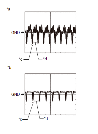
| *a | Waveform 1 |
| *b | Waveform 2 |
| *c | Synchronization Signal |
| *d | Video Waveform |
(1) Waveform 1
| Item | Content |
|---|---|
| Terminal No. (Symbol) | Y25-3 (CV+) - Y25-2 (CV-) |
| Tool Setting | 200 mV/DIV., 50 μsec./DIV. |
| Condition | Power switch on (IG), shift lever in R, camera lens is not covered, displaying an image |
HINT:
The video waveform changes according to the image sent by the rear television camera assembly.
(2) Waveform 2
| Item | Content |
|---|---|
| Terminal No. (Symbol) | Y25-3 (CV+) - Y25-2 (CV-) |
| Tool Setting | 200 mV/DIV., 50 μsec./DIV. |
| Condition | Power switch on (IG), shift lever in R, camera lens is covered, blacking out screen |
HINT:
The video waveform changes according to the image sent by the rear television camera assembly.
READ NEXT:
 Diagnosis System
DIAGNOSIS SYSTEM PARKING ASSIST MONITOR DIAGNOSIS SYSTEM (a) For parking assist monitor system diagnosis, signals received by the radio receiver assembly can be checked and the parking assist monitor
Dtc Check / Clear
DTC CHECK / CLEAR CHECK DTC (a) Connect the Techstream to the DLC3. (b) Turn the power switch on (IG). (c) Turn the Techstream on. (d) Enter the following menus: Chassis / Parking Assist Camera / Trou
Data List / Active Test
DATA LIST / ACTIVE TEST DATA LIST NOTICE: In the table below, the values listed under "Normal Condition" are reference values. Do not depend solely on these reference values when deciding whether a pa
SEE MORE:
Rear Window Defogger System does not Operate
DESCRIPTION When the rear window defogger switch on the air conditioning control assembly is pressed, the operation signal is transmitted to the air conditioning amplifier assembly via LIN communication. When the air conditioning amplifier assembly receives the signal, it turns on the defogger relay
Customize Parameters
CUSTOMIZE PARAMETERS CUSTOMIZE POWER MIRROR CONTROL SYSTEM HINT: The following items can be customized. NOTICE:
When the customer requests a change in a function, first make sure that the function can be customized.
Record the current settings before customizing.
(a) Customizing with the Tec
