Lexus NX: Terminals Of Ecu
Lexus NX Service Manual / Audio & Visual & Telematics / Telematics / Telematics System / Terminals Of Ecu
TERMINALS OF ECU
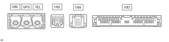
DCM (TELEMATICS TRANSCEIVER)
| Terminal No. (Symbol) | Wiring Color | Terminal Description | Condition | Specified Condition |
|---|---|---|---|---|
| I183-1 (+B) - I183-20 (E) | Y - W-B | Power source (+B) | Power switch off | 11 to 14 V |
| I183-20 (E) - Body ground | W-B - Body ground | Ground | Always | Below 1 Ω |
| I183-19 (IG2) - I183-20 (E) | R - W-B | Power source (IG) | Power switch on (IG) | 11 to 14 V |
| Power switch off | Below 1 V | |||
| I183-25 (CANP) | Y | CAN communication signal | - | - |
| I183-26 (CANN) | W | CAN communication signal | - | - |
| I183-30 (SLPD) - I183-20 (E) | L - W-B | Steering lock bar position signal | Steering locked | 11 to 14 V |
| Steering unlocked | Below 1.5 V |
CERTIFICATION ECU (SMART KEY ECU ASSEMBLY)
Click here .gif)
READ NEXT:
 Dtc Check / Clear
DTC CHECK / CLEAR CHECK DTC (a) Connect the Techstream to the DLC3. (b) Turn the power switch on (IG). (c) Turn the Techstream on. (d) Enter the following menus: Body Electrical / Telematics / Trouble
Data List / Active Test
DATA LIST / ACTIVE TEST NOTICE: In the table below, the values listed under "Normal Condition" are reference values. Do not depend solely on these reference values when deciding whether a part is faul
Diagnostic Trouble Code Chart
DIAGNOSTIC TROUBLE CODE CHART Telematics System DTC No. Detection Item Link U014087 Lost Communication with Body Control Module Missing Message U015587 Lost Communication with
SEE MORE:
Precaution
PRECAUTION PRECAUTIONS FOR FRONT CAMERA SYSTEM (a) Characteristics of forward recognition camera (1) The forward recognition camera has characteristics similar to human eyes. In conditions where the front is hard to see for the driver, the forward recognition camera will similarly have difficulties
Removal
REMOVAL CAUTION / NOTICE / HINT HINT:
Use the same procedure for the RH and LH sides.
The procedure listed below is for the LH side.
PROCEDURE 1. REMOVE FRONT SEAT ASSEMBLY LH Click here 2. REMOVE FRONT LOWER SEAT CUSHION SHIELD Click here 3. REMOVE POWER SEAT SWITCH KNOB LH Click here
© 2016-2026 Copyright www.lexunx.com
