Lexus NX: Side Camera Feedback Malfunction (C1683)
DESCRIPTION
This DTC is stored if the parking assist ECU judges as a result of its self check that a synchronization problem is occurring in the image signal sent from the passenger side television camera assembly to the parking assist ECU.
| DTC No. | Detection Item | DTC Detection Condition | Trouble Area |
|---|---|---|---|
| C1683 | Side Camera Feedback Malfunction | Side camera feedback malfunction |
|
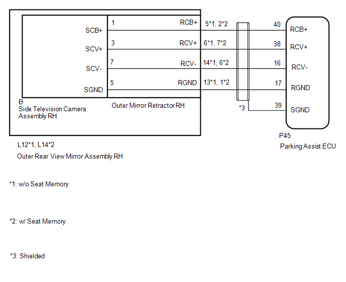
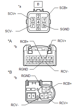
WIRING DIAGRAM
CAUTION / NOTICE / HINT
NOTICE:
-
When "!" mark is displayed on the multi-display assembly after the cable is disconnected from the negative (-) auxiliary battery terminal, correct the steering angle neutral point.
Click here
.gif)
-
Depending on the parts that are replaced or operations that are performed during vehicle inspection or maintenance, calibration of other systems as well as the panoramic view monitor system may be needed.
Click here
PROCEDURE
| 1. | CHECK FOR DTC |
(a) Clear the DTCs.
Click here
(b) Check for DTCs.
Click here
OK:
DTC C1683 is not output.
| Result | Proceed to |
|---|---|
| OK | A |
| NG | B |
| A | .gif) | USE SIMULATION METHOD TO CHECK |
|
.gif)
| 2. | CHECK HARNESS AND CONNECTOR (PARKING ASSIST ECU - OUTER REAR VIEW MIRROR ASSEMBLY RH) |
(a) Disconnect the P45 parking assist ECU connector.
(b) Disconnect the L12*1 or L14*2 outer rear view mirror assembly RH connector.
- *1: w/o Seat Memory
- *2: w/ Seat Memory
(c) Measure the resistance according to the value(s) in the table below.
Standard Resistance:
w/o Seat Memory| Tester Connection | Condition | Specified Condition |
|---|---|---|
| P45-40 (RCB+) - L12-5 (RCB+) | Always | Below 1 Ω |
| P45-38 (RCV+) - L12-6 (RCV+) | Always | Below 1 Ω |
| P45-16 (RCV-) - L12-14 (RCV-) | Always | Below 1 Ω |
| P45-17 (RGND) - L12-13 (RGND) | Always | Below 1 Ω |
| P45-40 (RCB+) or L12-5 (RCB+) - Body ground | Always | 10 kΩ or higher |
| P45-38 (RCV+) or L12-6 (RCV+) - Body ground | Always | 10 kΩ or higher |
| P45-16 (RCV-) or L12-14 (RCV-) - Body ground | Always | 10 kΩ or higher |
| P45-17 (RGND) or L12-13 (RGND) - Body ground | Always | 10 kΩ or higher |
| P45-39 (SGND) - Body ground | Always | 10 kΩ or higher |
| Tester Connection | Condition | Specified Condition |
|---|---|---|
| P45-40 (RCB+) - L14-2 (RCB+) | Always | Below 1 Ω |
| P45-38 (RCV+) - L14-7 (RCV+) | Always | Below 1 Ω |
| P45-16 (RCV-) - L14-6 (RCV-) | Always | Below 1 Ω |
| P45-17 (RGND) - L14-1 (RGND) | Always | Below 1 Ω |
| P45-40 (RCB+) or L14-2 (RCB+) - Body ground | Always | 10 kΩ or higher |
| P45-38 (RCV+) or L14-7 (RCV+) - Body ground | Always | 10 kΩ or higher |
| P45-16 (RCV-) or L14-6 (RCV-) - Body ground | Always | 10 kΩ or higher |
| P45-17 (RGND) or L14-1 (RGND) - Body ground | Always | 10 kΩ or higher |
| P45-39 (SGND) - Body ground | Always | 10 kΩ or higher |
| NG | | REPAIR OR REPLACE HARNESS OR CONNECTOR |
|
| 3. | CHECK PARKING ASSIST ECU (RCV-, RGND) |
| (a) Disconnect the parking assist ECU connector. |
|
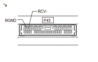
(b) Measure the resistance according to the value(s) in the table below.
Standard Resistance:
| Tester Connection | Condition | Specified Condition |
|---|---|---|
| 17 (RGND) - Body ground | Always | Below 1 Ω |
| 16 (RCV-) - Body ground | Always | Below 1 Ω |
| NG | | REPLACE PARKING ASSIST ECU |
|
| 4. | CHECK PARKING ASSIST ECU (RCB+, RGND) |
| (a) Disconnect the outer rear view mirror assembly RH connector. |
|
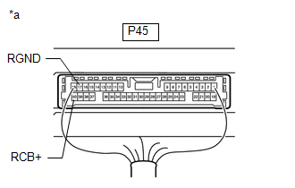
(b) Measure the voltage according to the value(s) in the table below.
Standard Voltage:
| Tester Connection | Switch Condition | Specified Condition |
|---|---|---|
| P45-40 (RCB+) - P45-17 (RGND) | Power switch on (IG) | 5.5 to 7.05 V |
| P45-40 (RCB+) - P45-17 (RGND) | Power switch off | Below 1 V |
| NG | | REPLACE PARKING ASSIST ECU |
|
| 5. | CHECK SIDE TELEVISION CAMERA ASSEMBLY RH (RCV+, RGND) |
(a) Remove the parking assist ECU with the connector still connected.
(b) Using an oscilloscope, check the waveform of the side television camera assembly RH.
HINT:
A waterproof connector is used for the side television camera assembly RH. Therefore, inspect the waveform at the parking assist ECU with the connector connected.
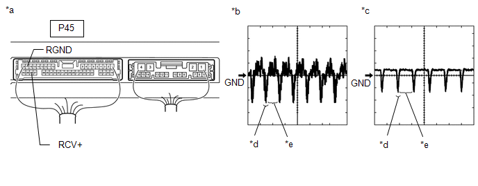
| *a | Component with harness connected (Parking Assist ECU) | *b | Waveform 1 (camera lens not covered, displaying an image) |
| *c | Waveform 2 (camera lens covered, blacking out the screen) | *d | Synchronization Signal |
| *e | Video Waveform | - | - |
HINT:
- The video waveform changes according to the image sent by the side television camera assembly RH.
- The video waveform is constantly output when the power switch is on (ACC).
| Item | Content |
|---|---|
| Tester Connection | P45-38 (RCV+) - P45-17 (RGND) |
| Tool Setting | 200 mV/DIV., 50 μsec./DIV. |
| Condition | Power switch on (IG), panoramic view monitor switch on |
OK:
Waveform is similar to that shown in illustration.
| OK | | REPLACE PARKING ASSIST ECU |
|
| 6. | INSPECT OUTER MIRROR RETRACTOR RH |
| (a) Remove the outer mirror retractor RH. Click here |
|
(b) Measure the resistance according to the value(s) in the table below.
Standard Resistance:
w/o Seat Memory| Tester Connection | Condition | Specified Condition |
|---|---|---|
| B-1 (SCB+) - 5 (RCB+) | Always | Below 1 Ω |
| B-3 (SCV+) - 6 (RCV+) | Always | Below 1 Ω |
| B-7 (SCV-) - 14 (RCV-) | Always | Below 1 Ω |
| B-5 (SGND) - 13 (RGND) | Always | Below 1 Ω |
| B-1 (SCB+) or 5 (RCB+) - Body ground | Always | 10 kΩ or higher |
| B-3 (SCV+) or 6 (RCV+) - Body ground | Always | 10 kΩ or higher |
| B-7 (SCV-) or 14 (RCV-) - Body ground | Always | 10 kΩ or higher |
| B-5 (SGND) or 13 (RGND) - Body ground | Always | 10 kΩ or higher |
| Tester Connection | Condition | Specified Condition |
|---|---|---|
| B-1 (SCB+) - 2 (RCB+) | Always | Below 1 Ω |
| B-3 (SCV+) - 7 (RCV+) | Always | Below 1 Ω |
| B-7 (SCV-) - 6 (RCV-) | Always | Below 1 Ω |
| B-5 (SGND) - 1 (RGND) | Always | Below 1 Ω |
| B-1 (SCB+) or 2 (RCB+) - Body ground | Always | 10 kΩ or higher |
| B-3 (SCV+) or 7 (RCV+) - Body ground | Always | 10 kΩ or higher |
| B-7 (SCV-) or 6 (RCV-) - Body ground | Always | 10 kΩ or higher |
| B-5 (SGND) or 1 (RGND) - Body ground | Always | 10 kΩ or higher |
| NG | | REPLACE OUTER MIRROR RETRACTOR RH |
|
| 7. | REPLACE SIDE TELEVISION CAMERA ASSEMBLY RH |
(a) Replace the side television camera assembly RH with a new or normally functioning one.
Click here
|
| 8. | CHECK FOR DTC |
(a) Clear the DTCs.
Click here
(b) Check for DTCs.
Click here
OK:
DTC C1683 is not output.
| OK | | END (SIDE TELEVISION CAMERA ASSEMBLY LH IS DEFECTIVE) |
| NG | | REPLACE PARKING ASSIST ECU |
READ NEXT:
 Side Camera Current Malfunction (C1684)
DESCRIPTION This DTC is stored if the parking assist ECU judges as a result of its self check that a synchronization problem is occurring in the image signal sent from the passenger side television ca
Driver Side Camera Video Sync Signal Malfunction (C1686)
DESCRIPTION This DTC is stored if the parking assist ECU judges as a result of its self check that a synchronization problem is occurring in the image signal sent from the driver side television camer
Over Current Detected in Driver Side Camera (C1687)
DESCRIPTION This DTC is stored if the parking assist ECU judges as a result of its self check that a synchronization problem is occurring in the image signal sent from the driver side television camer
SEE MORE:
Generator Inverter Temperature Sensor Circuit Range / Performance (P0BCD-315,P0BD0-314)
DTC SUMMARY MALFUNCTION DESCRIPTION These DTCs indicate the temperature sensor value for generator inverter is abnormal. The cause of this malfunction may be one of the following: Internal inverter malfunction
Inverter with converter assembly internal circuit malfunction
Hybrid cooling system
Voice Recognition Microphone Disconnected (B1579)
DESCRIPTION The radio receiver assembly and telephone microphone assembly are connected to each other using the microphone connection detection signal lines. This DTC is stored when a microphone connection detection signal line is disconnected. DTC No. Detection Item DTC Detection Condition
