- Steering Unlock Switch
Lexus NX: Steering Lock Position Signal Circuit Malfunction (B2285)
Lexus NX Service Manual / Vehicle Interior / Theft Deterrent / Keyless Entry / Smart Access System With Push-button Start (for Start Function) / Steering Lock Position Signal Circuit Malfunction (B2285)
DESCRIPTION
This DTC is stored when the steering lock position signal sent by the steering lock ECU (steering lock actuator assembly) via direct line and the steering lock position signal sent via LIN communication do not match.
| DTC No. | Detection Item | DTC Detection Condition | Trouble Area | Note |
|---|---|---|---|---|
| B2285 | Steering Lock Position Signal Circuit Malfunction | The steering lock position signal sent by the steering lock ECU (steering lock actuator assembly) via direct line and the steering lock position signal sent via LIN communication do not match. (1-trip detection logic*1) |
|
|
- *1: Only detected while a malfunction is present and the power switch is on (IG).
- *2: for Lexus Enform Remote Compatible Type
| Vehicle Condition when Malfunction Detected | Fail-safe Function when Malfunction Detected |
|---|---|
| The hybrid control system cannot be started. | The ECU does not send a hybrid control system start request. |
| DTC No. | Data List and Active Test |
|---|---|
| B2285 | Power Source Control Smart Access
|
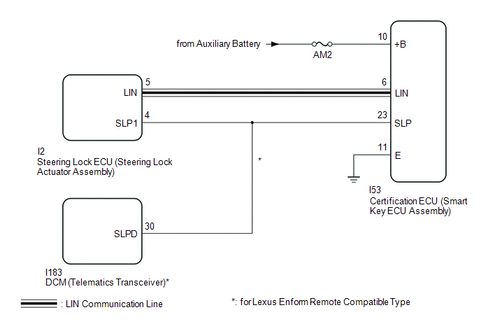
WIRING DIAGRAM
CAUTION / NOTICE / HINT
NOTICE:
- When using the Techstream with the power switch off, connect the Techstream to the DLC3 and turn a courtesy light switch on and off at intervals of 1.5 seconds or less until communication between the Techstream and the vehicle begins. Then select the vehicle type under manual mode and enter the following menus: Body Electrical / Smart Access. While using the Techstream, periodically turn a courtesy light switch on and off at intervals of 1.5 seconds or less to maintain communication between the Techstream and the vehicle.
-
The smart access system with push-button start (for Start Function) uses the LIN communication system and CAN communication system. Inspect the communication function by following How to Proceed with Troubleshooting. Troubleshoot the smart access system with push-button start (for Start Function) after confirming that the communication systems are functioning properly.
Click here
.gif)
- Inspect the fuses of circuits related to this system before performing the following procedure.
-
Before replacing the certification ECU (smart key ECU assembly), steering lock ECU (steering lock actuator assembly) or DCM (Telematics Transceiver)*, refer to the smart access system with push-button start (for Start Function) Precaution.
Click here
-
After repair, confirm that no DTCs are output by performing "DTC Output Confirmation Operation".
- *: for Lexus Enform Remote Compatible Type
HINT:
When the cable is disconnected and reconnected to the negative (-) auxiliary battery terminal, the power source mode returns to the state it was in before the cable was disconnected.
PROCEDURE
| 1. | CHECK FOR DTC |
(a) Check for DTCs.
Body Electrical > Smart Access > Trouble CodesHINT:
- If the steering cannot be unlocked, the power switch cannot be turned on (IG) and the hybrid control system cannot be started.
- If LIN communication is not available, the steering cannot be locked or unlocked.
OK:
LIN communication system DTC B2785 is not output simultaneously.
| NG | .gif) | GO TO DTC B2785 |
|
.gif)
| 2. | READ VALUE USING TECHSTREAM (STEERING UNLOCK SWITCH) |
(a) Connect the Techstream to the DLC3.
(b) Turn the power switch on (IG).
(c) Turn the Techstream on.
(d) Enter the following menus: Body Electrical / Power Source Control / Data List.
(e) Read the Data List according to the display on the Techstream.
Body Electrical > Power Source Control > Data List| Tester Display | Measurement Item | Range | Normal Condition | Diagnostic Note |
|---|---|---|---|---|
| Steering Unlock Switch | State of steering unlock sensor signal output from steering lock ECU (steering lock actuator assembly) | OFF or ON | OFF: Steering locked ON: Steering unlocked |
|
| Tester Display |
|---|
| Steering Unlock Switch |
| Result | Proceed to |
|---|---|
| Techstream display does not change | A |
| Techstream display changes | B |
| B | | REPLACE STEERING LOCK ECU (STEERING LOCK ACTUATOR ASSEMBLY) |
|
| 3. | CHECK HARNESS AND CONNECTOR (POWER SOURCE) |
Click here
| NG | | REPAIR OR REPLACE HARNESS OR CONNECTOR IN CIRCUIT CONNECTED TO POWER SOURCE |
|
| 4. | CHECK HARNESS AND CONNECTOR (GROUND) |
Click here
| NG | | REPAIR OR REPLACE HARNESS OR CONNECTOR |
|
| 5. | CONFIRM MODEL |
(a) Choose the model to be inspected.
| Result | Proceed to |
|---|---|
| except Lexus Enform Remote Compatible Type | A |
| for Lexus Enform Remote Compatible Type | B |
| B | | GO TO STEP 8 |
|
| 6. | CHECK STEERING LOCK ECU (STEERING LOCK ACTUATOR ASSEMBLY) |
(a) Reconnect the I53 certification ECU (smart key ECU assembly) connector.
| (b) Measure the resistance according to the value(s) in the table below. Standard Resistance:
HINT:
|
| ||||||||||||
| NG | | REPLACE STEERING LOCK ECU (STEERING LOCK ACTUATOR ASSEMBLY) |
|
| 7. | CHECK HARNESS AND CONNECTOR (CERTIFICATION ECU (SMART KEY ECU ASSEMBLY) - STEERING LOCK ECU (STEERING LOCK ACTUATOR ASSEMBLY)) |
(a) Disconnect the I53 certification ECU (smart key ECU assembly) connector.
(b) Disconnect the I2 steering lock ECU (steering lock actuator assembly) connector.
(c) Measure the resistance according to the value(s) in the table below.
Standard Resistance:
| Tester Connection | Condition | Specified Condition |
|---|---|---|
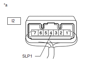
| I53-23 (SLP) - I2-4 (SLP1) | Always | Below 1 Ω |
| I53-23 (SLP) or I2-4 (SLP1) - Body ground | Always | 10 kΩ or higher |
| OK | | REPLACE CERTIFICATION ECU (SMART KEY ECU ASSEMBLY) |
| NG | | REPAIR OR REPLACE HARNESS OR CONNECTOR |
| 8. | CHECK HARNESS AND CONNECTOR (CERTIFICATION ECU (SMART KEY ECU ASSEMBLY) - STEERING LOCK ECU (STEERING LOCK ACTUATOR ASSEMBLY) - DCM) |
(a) Disconnect the I53 certification ECU (smart key ECU assembly) connector.
(b) Disconnect the I2 steering lock ECU (steering lock actuator assembly) connector.
(c) Disconnect the I183 DCM (telematics transceiver) connector.
(d) Measure the resistance according to the value(s) in the table below.
Standard Resistance:
| Tester Connection | Condition | Specified Condition |
|---|---|---|
| I53-23 (SLP) - I2-4 (SLP1) | Always | Below 1 Ω |
| I2-4 (SLP1) - I183-30 (SLPD) | Always | Below 1 Ω |
| I53-23 (SLP) or I2-4 (SLP1) or I183-30 (SLPD) - Body ground | Always | 10 kΩ or higher |
(e) Measure the voltage according to the value(s) in the table below.
Standard Voltage:
| Tester Connection | Condition | Specified Condition |
|---|---|---|
| I53-23 (SLP) or I2-4 (SLP1) or I183-30 (SLPD) - Body ground | Always | Below 1 V |
| NG | | REPAIR OR REPLACE HARNESS OR CONNECTOR |
|
| 9. | INSPECT STEERING LOCK ECU (STEERING LOCK ACTUATOR ASSEMBLY) |
(a) Reconnect the I2 steering lock ECU (steering lock actuator assembly) connector.
(b) Reconnect the I53 certification ECU (smart key ECU assembly) connector.
| (c) Measure the resistance according to the value(s) in the table below. Standard Resistance:
HINT:
|
| ||||||||||||
| NG | | REPLACE STEERING LOCK ECU (STEERING LOCK ACTUATOR ASSEMBLY) |
|
| 10. | INSPECT CERTIFICATION ECU (SMART KEY ECU ASSEMBLY) |
(a) Check the push-button start function.
(1) Enter the vehicle while carrying an electrical key transmitter sub-assembly.
(2) Depress the brake pedal with the shift lever in P.
(3) Check that the hybrid system turns on (READY) when the power switch is pressed.
OK:
Power source mode becomes on (READY).
HINT:
Check the steering lock ECU (steering lock actuator assembly) and certification ECU (smart key ECU assembly) connectors connected.
| OK | | REPLACE DCM (TELEMATICS TRANSCEIVER) |
| NG | | REPLACE CERTIFICATION ECU (SMART KEY ECU ASSEMBLY) |
READ NEXT:
 Lost Communication with Main Body ECU (U0140,U0142,U0155,U0293,U1117)
DESCRIPTION These DTCs are stored when there is a CAN communication error between the hybrid vehicle control ECU, certification ECU (smart key ECU assembly), ECM, main body ECU (multiplex network body
Power Source Mode does not Change to ON (IG)
DESCRIPTION If the power switch is pressed with the electrical key transmitter sub-assembly in the cabin, the certification ECU (smart key ECU assembly) receives a signal and changes the power source
Power Source Mode does not Change to ON (ACC)
DESCRIPTION If the power switch is pressed with the electrical key transmitter sub-assembly in the cabin, the certification ECU (smart key ECU assembly) receives a signal and changes the power source
SEE MORE:
Diagnosis System
DIAGNOSIS SYSTEM DESCRIPTION (a) Intelligent clearance sonar system data and Diagnostic Trouble Codes (DTCs) can be read from the Data Link Connector 3 (DLC3) of the vehicle. When the system seems to be malfunctioning, use the Techstream to check for malfunctions and to repair them. CHECK DLC3 (a) C
Components
COMPONENTS ILLUSTRATION *1 INNER REAR VIEW MIRROR ASSEMBLY *2 NO. 1 FORWARD RECOGNITION COVER *3 NO. 2 FORWARD RECOGNITION COVER - - N*m (kgf*cm, ft.*lbf): Specified torque - -
© 2016-2026 Copyright www.lexunx.com
