Lexus NX: Terminals Of Ecu
TERMINALS OF ECU
TERMINALS OF ECU
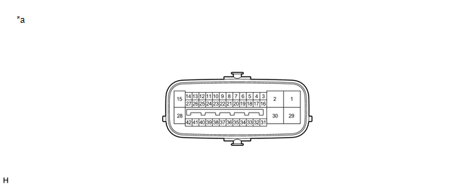
| *a | Component without harness connected (Skid Control ECU (Brake Booster with Master Cylinder Assembly)) | - | - |
| Terminal No. (Symbol) | Terminal Description |
|---|---|
| 1 (MRI1) | Motor power supply input 1 |
| 2 (MRI2) | Motor power supply input 2 |
| 3 (STPO) | Stop light control ECU assembly output |
| 4 | - (Not used) |
| 5 (FR-) | Front speed sensor RH (-) signal input |
| 6 (STP2) | Stop light control ECU assembly input |
| 7 (RL-) | Rear speed sensor LH (-) signal input |
| 8 (CSW) | VSC OFF switch (Integration control and panel assembly) input |
| 9 (RR-) | Rear speed sensor RH (-) signal input |
| 10 (HZRI) | Brake hold switch (Integration control and panel assembly) input |
| 11 (SP1) | Speed sensor signal output |
| 12 (IG2) | IG2 power source input |
| 13 | - (Not used) |
| 14 (BI) | +B power source input |
| 15 (BS) | Solenoid power supply input |
| 16 (IG1) | IG1 power source input |
| 17 | - (Not used) |
| 18 (FR+) | Front speed sensor RH (+) power supply output |
| 19 (CTY) | Front door courtesy light switch assembly input |
| 20 (RL+) | Rear speed sensor LH (+) power supply output |
| 21 | - (Not used) |
| 22 (RR+) | Rear speed sensor RH (+) power supply output |
| 23 (GND6) | Skid control ECU (Brake booster with master cylinder assembly) ground 6 |
| 24 (GND5) | Skid control ECU (Brake booster with master cylinder assembly) ground 5 |
| 25 (GND4) | Skid control ECU (Brake booster with master cylinder assembly) ground 4 |
| 26 (GND3) | Skid control ECU (Brake booster with master cylinder assembly) ground 3 |
| 27 (GND2) | Skid control ECU (Brake booster with master cylinder assembly) ground 2 |
| 28 (GND) | Skid control ECU (Brake booster with master cylinder assembly) ground |
| 29 (MRO1) | Motor power supply output 1 |
| 30 (MRO2) | Motor power supply output 2 |
| 31 (FL+) | Front speed sensor LH (+) power supply output |
| 32 (FL-) | Front speed sensor LH (-) signal input |
| 33 (STP) | Stop light switch assembly input |
| 34 (CA2L) | CAN communication line 2 (L) |
| 35 (CA2H) | CAN communication line 2 (H) |
| 36 (LBL) | Brake fluid level warning switch input |
| 37 (CA1H) | CAN communication line 1 (H) |
| 38 (CA1L) | CAN communication line 1 (L) |
| 39 (VCSK) | Brake pedal stroke sensor assembly power supply output |
| 40 (SKS2) | Brake pedal stroke sensor assembly signal input 2 |
| 41 (SKG) | Brake pedal stroke sensor assembly ground |
| 42 (SKS) | Brake pedal stroke sensor assembly signal input |
TERMINAL INSPECTION
(a) Disconnect the connector and measure the voltage or resistance on the wire harness side.
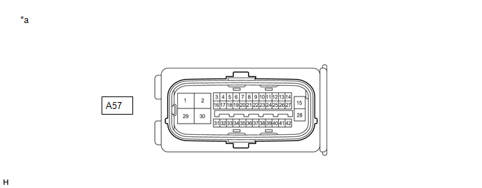
| *a | Front view of wire harness connector (to Skid Control ECU (Brake Booster with Master Cylinder Assembly)) | - | - |
HINT:
The voltage cannot be measured with the connector connected to the skid control ECU (brake booster with master cylinder assembly) as the connector is watertight.
Standard| Terminal No. (Symbol) | Wiring Color | Terminal Description | Condition | Specified Condition |
|---|---|---|---|---|
| A57-1 (MRI1) - Body ground | B - Body ground | Motor power supply input 1 | Always | 11 to 14 V |
| A57-2 (MRI2) - Body ground | R - Body ground | Motor power supply input 2 | Always | 11 to 14 V |
| A57-3 (STPO) - Body ground | R - Body ground | Stop light control ECU assembly output | Power switch on (IG) | 11 to 14 V |
| A57-6 (STP2) - Body ground | L - Body ground | Stop light control ECU assembly input | Brake pedal depressed → released | 11 to 14 V → Below 1.5 V |
| A57-8 (CSW) - Body ground | L - Body ground | VSC OFF switch (Integration control and panel assembly) input | VSC OFF switch (integration control and panel assembly) pressed and held → released | Below 1 Ω → 10 kΩ or higher |
| A57-10 (HZRI) - Body ground | R - Body ground | Brake hold switch (Integration control and panel assembly) input | Brake hold switch (integration control and panel assembly) pressed and held → released | Below 1 Ω → 10 kΩ or higher |
| A57-12 (IG2) - Body ground | B - Body ground | IG2 power source input | Power switch on (IG) | 11 to 14 V |
| A57-14 (BI) - Body ground | B - Body ground | +B power source input | Always | 11 to 14 V |
| A57-15 (BS) - Body ground | B - Body ground | Solenoid power supply input | Always | 11 to 14 V |
| A57-16 (IG1) - Body ground | L - Body ground | IG1 power source input | Power switch on (IG) | 11 to 14 V |
| A57-19 (CTY) - Body ground | W - Body ground | Front door courtesy light switch assembly input | Driver door closed → open | Pulse generation → Below 1.5 V |
| A57-23 (GND6) - Body ground | W-B - Body ground | Skid control ECU (Brake booster with master cylinder assembly) ground 6 | Always | Below 1 Ω |
| A57-24 (GND5) - Body ground | W-B - Body ground | Skid control ECU (Brake booster with master cylinder assembly) ground 5 | Always | Below 1 Ω |
| A57-25 (GND4) - Body ground | W-B - Body ground | Skid control ECU (Brake booster with master cylinder assembly) ground 4 | Always | Below 1 Ω |
| A57-26 (GND3) - Body ground | W-B - Body ground | Skid control ECU (Brake booster with master cylinder assembly) ground 3 | Always | Below 1 Ω |
| A57-27 (GND2) - Body ground | W-B - Body ground | Skid control ECU (Brake booster with master cylinder assembly) ground 2 | Always | Below 1 Ω |
| A57-28 (GND) - Body ground | W-B - Body ground | Skid control ECU (Brake booster with master cylinder assembly) ground | Always | Below 1 Ω |
| A57-33 (STP) - Body ground | LG - Body ground | Stop light switch assembly input | Stop light switch assembly on → off (Brake pedal depressed → released) | 11 to 14 V → Below 1.5 V |
| A57-36 (LBL) - Body ground | V - Body ground | Brake fluid level warning switch input | Brake fluid level warning switch off → on | 1.84 to 2.16 kΩ → Below 1 Ω |
READ NEXT:
 Diagnosis System
DIAGNOSIS SYSTEM DESCRIPTION When troubleshooting a vehicle with a diagnosis system, the only difference from the usual troubleshooting procedure is connecting the Techstream to the vehicle and readin
Dtc Check / Clear
DTC CHECK / CLEAR DTC CHECK/CLEAR (a) Check for DTCs. (1) Connect the Techstream to the DLC3. (2) Turn the power switch on (IG). (3) Turn the Techstream on. (4) Read the DTCs following the prompts on
Freeze Frame Data
FREEZE FRAME DATA FREEZE FRAME DATA/INFORMATION (a) Using the Techstream, check the vehicle condition (ECU, sensor) when the brake system operates or a DTC is output. (b) The freeze frame data that is
SEE MORE:
Brake Hold Standby Indicator Light Circuit
DESCRIPTION The brake hold standby indicator light turns on if brake hold control is possible when the following conditions required for operation standby are met and the brake hold switch (integration control and panel assembly) is turned on while the power switch is on (IG).
Conditions required
Disassembly
DISASSEMBLY PROCEDURE 1. REMOVE AIR FILTER CASE (a) Detach the claw and guide and remove the air filter case. 2. REMOVE AIR REFINER ELEMENT (a) Remove the air refiner element. 3. REMOVE BLOWER WITH FAN MOTOR SUB-ASSEMBLY (a) Remove the 3 screws and the blower with fa
