- DTC judgment completed
- System normal
Lexus NX: Throttle Actuator Control Motor Current Range / Performance (P2118)
Lexus NX Service Manual / Engine & Hybrid System / 2ar-fxe (engine Control) / Sfi System / Throttle Actuator Control Motor Current Range / Performance (P2118)
DESCRIPTION
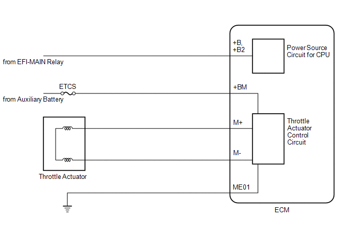
The electronic throttle control system has a dedicated power supply circuit. The voltage (+BM) is monitored and when it is low (less than 4 V), the ECM determines that there is a malfunction in the electronic throttle control system and cuts off the current to the throttle actuator.
When the voltage becomes unstable, the electronic throttle control system itself becomes unstable. For this reason, when the voltage is low, the current to the throttle actuator is cut. If repairs are made and the system returns to normal, turn the power switch off. The ECM then allows the current to flow to the throttle actuator so that it can be restarted.
HINT:
The electronic throttle control system does not use a throttle cable.
| DTC No. | Detection Item | DTC Detection Condition | Trouble Area | MIL | Memory |
|---|---|---|---|---|---|
| P2118 | Throttle Actuator Control Motor Current Range / Performance | An open in the electronic throttle control system power source (+BM) circuit (1 trip detection logic). |
| Comes on | DTC stored |
MONITOR DESCRIPTION
The ECM monitors the auxiliary battery supply voltage applied to the throttle actuator.
When the power supply voltage (+BM) is less than 4 V for 0.8 seconds or more, the ECM interprets this as an open in the power supply circuit (+BM). The ECM then illuminates the MIL and stores this DTC.
MONITOR STRATEGY
| Related DTCs | P2118: Electronic throttle actuator power supply line range check (low voltage) |
| Required Sensors/Components (Main) | Throttle actuator Throttle valve (throttle body with motor assembly) ETCS fuse |
| Required Sensors/Components (Related) | - |
| Frequency of Operation | Continuous |
| Duration | 0.8 seconds |
| MIL Operation | Immediate |
| Sequence of Operation | None |
TYPICAL ENABLING CONDITIONS
| Monitor runs whenever the following DTCs are not stored | None |
| Both of the following conditions are met | - |
| Command to electronic throttle actuator power | On |
| Auxiliary battery voltage | 8 V or higher |
TYPICAL MALFUNCTION THRESHOLDS
| Electronic throttle actuator power supply voltage | Less than 4 V |
COMPONENT OPERATING RANGE
| Electronic throttle control | Normal |
CONFIRMATION DRIVING PATTERN
- Connect the Techstream to the DLC3.
- Turn the power switch on (IG) and turn the Techstream on.
- Clear the DTCs (even if no DTCs are stored, perform the clear DTC procedure).
- Turn the power switch off and wait for at least 30 seconds.
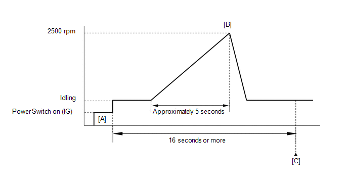
- Turn the power switch on (IG) and turn the Techstream on [A].
-
Put the engine in inspection mode (maintenance mode).
Click here
.gif)
- Start the engine.
-
Slowly depress the accelerator pedal, raise the engine speed to approximately 2500 rpm over approximately 5 seconds, and then idle the engine [B].
HINT:
During charging control, the engine speed is set at idle. Therefore, the engine speed does not increase when depressing the accelerator pedal. In this case, perform step [B] after charging control has completed.
- Check that 16 seconds or more have elapsed since the engine was started.
- Enter the following menus: Powertrain / Engine and ECT / Trouble Codes [C].
-
Read the pending DTCs.
HINT:
- If a pending DTC is output, the system is malfunctioning.
- If a pending DTC is not output, perform the following procedure.
- Enter the following menus: Powertrain / Engine and ECT / Utility / All Readiness.
- Input the DTC: P2118.
-
Check the DTC judgment result.
Techstream Display
Description
NORMAL
ABNORMAL
- DTC judgment completed
- System abnormal
INCOMPLETE
- DTC judgment not completed
- Perform driving pattern after confirming DTC enabling conditions
N/A
- Unable to perform DTC judgment
- Number of DTCs which do not fulfill DTC preconditions has reached ECU memory limit
HINT:
- If the judgment result shows NORMAL, the system is normal.
- If the judgment result shows ABNORMAL, the system has a malfunction.
- If the judgment result shows INCOMPLETE or N/A, perform steps [B] and [C] again.
-
If no pending DTC is output, perform a universal trip and check for permanent DTCs.
Click here
HINT:
- If a permanent DTC is output, the system is malfunctioning.
- If no permanent DTC is output, the system is normal.
FAIL-SAFE
When this DTC or other DTCs relating to Electronic Throttle Control System (ETCS) malfunctions are stored, the ECM enters fail-safe mode. During fail-safe mode, the ECM cuts the current to the throttle actuator, and the throttle valve is returned to a 5.5° throttle valve opening angle by the return spring. The ECM stops the engine and the vehicle can be driven using solely the hybrid system. If the accelerator pedal is depressed firmly and gently, the vehicle can be driven slowly.
Fail-safe mode continues until a pass condition is detected, and the power switch is then turned off.
WIRING DIAGRAM
Refer to DTC P2102.
Click here
CAUTION / NOTICE / HINT
NOTICE:
Inspect the fuses for circuits related to this system before performing the following procedure.
HINT:
Read freeze frame data using the Techstream. The ECM records vehicle and driving condition information as freeze frame data the moment a DTC is stored. When troubleshooting, freeze frame data can help determine if the vehicle was moving or stationary, if the engine was warmed up or not, if the air fuel ratio was lean or rich, and other data from the time the malfunction occurred.
PROCEDURE
| 1. | READ VALUE USING TECHSTREAM (+BM VOLTAGE) |
(a) Connect the Techstream to the DLC3.
(b) Turn the power switch on (IG).
(c) Turn the Techstream on.
(d) Enter the following menus: Powertrain / Engine and ECT / Data List / Gas Throttle / +BM Voltage.
Powertrain > Engine and ECT > Data List| Tester Display |
|---|
| +BM Voltage |
(e) Read the value displayed on the Techstream.
| Result | Proceed to |
|---|---|
| Less than 4 V | A |
| 11 to 16 V | B |
| B | .gif) | CHECK FOR INTERMITTENT PROBLEMS |
|
.gif)
| 2. | CHECK HARNESS AND CONNECTOR (ECM - AUXILIARY BATTERY, BODY GROUND) |
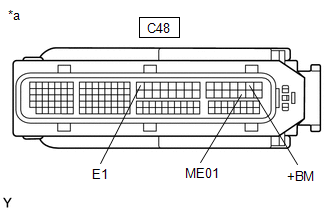
| *a | Front view of wire harness connector (to ECM) |
(a) Disconnect the ECM connector.
(b) Measure the voltage according to the value(s) in the table below.
Standard Voltage:
| Tester Connection | Condition | Specified Condition |
|---|---|---|
| C48-29 (+BM) - Body ground | Always | 11 to 16 V |
(c) Measure the resistance according to the value(s) in the table below.
Standard Resistance:
| Tester Connection | Condition | Specified Condition |
|---|---|---|
| C48-58 (ME01) - Body ground | Always | Below 1 Ω |
| C48-16 (E1) - Body ground | Always | Below 1 Ω |
| OK | | REPLACE ECM |
| NG | | REPAIR OR REPLACE HARNESS OR CONNECTOR |
READ NEXT:
 Throttle Actuator Control Throttle Body Range / Performance (P2119)
DESCRIPTION The electronic throttle control system is composed of the throttle actuator, throttle position sensor, and ECM. The ECM operates the throttle actuator to regulate the throttle valve in res
Oxygen (A/F) Sensor Signal Stuck Lean (Bank 1 Sensor 1) (P2195,P2196)
DESCRIPTION HINT: Although the DTC titles say oxygen sensor, these DTCs relate to the air fuel ratio sensor. The air fuel ratio sensor generates voltage* that corresponds to the actual air fuel ratio.
Bank 1 Air-Fuel Ratio Imbalance (P219A,P219C-P219F)
DESCRIPTION Refer to DTC P0300. Click here Refer to DTC P2195. Click here DTC No. Detection Item DTC Detection Condition Trouble Area MIL Memory P219A Bank 1 Air-Fuel Ratio Im
SEE MORE:
Initialization
INITIALIZATION DESCRIPTION (a) Perform initialization and calibration of the linear solenoid valve when the brake booster with master cylinder assembly, brake pedal stroke sensor assembly or brake pedal is replaced. Follow the procedure to perform initialization. HINT:
If there is a problem with
Components
COMPONENTS ILLUSTRATION *1 COWL SIDE TRIM BOARD LH *2 DOOR SCUFF PLATE ASSEMBLY LH *3 FRONT FLOOR CARPET ASSEMBLY *4 NO. 4 DASH PANEL INSULATOR PAD (FRONT FLOOR FOOTREST)
© 2016-2026 Copyright www.lexunx.com
