Lexus NX: Voice Recognition Microphone Disconnected (B1579)
DESCRIPTION
The radio receiver assembly and telephone microphone assembly are connected to each other using the microphone connection detection signal lines.
This DTC is stored when a microphone connection detection signal line is disconnected.
| DTC No. | Detection Item | DTC Detection Condition | Trouble Area |
|---|---|---|---|
| B1579 | Voice Recognition Microphone Disconnected | Telephone microphone signal is lost. |
|
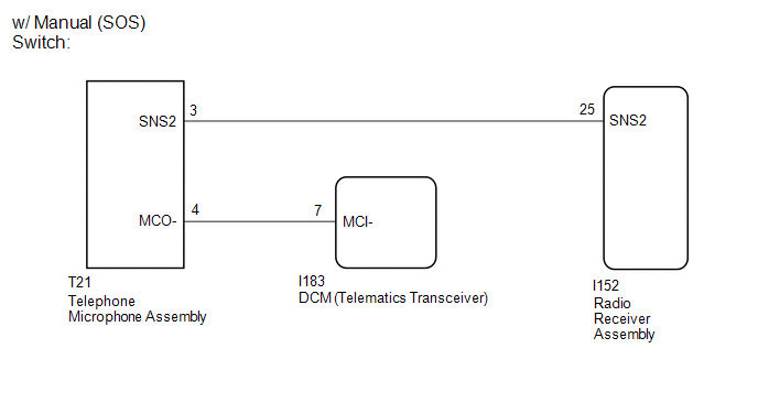
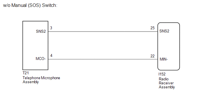
WIRING DIAGRAM
CAUTION / NOTICE / HINT
NOTICE:
-
When replacing the radio receiver assembly, always replace it with a new one.
If a radio receiver assembly which was installed to another vehicle is used, the following may occur:
- A communication malfunction DTC may be stored.
- The radio receiver assembly may not operate normally.
- When replacing the DCM (telematics transceiver), make sure to replace it with a new one (w/ Manual [SOS] Switch).
HINT:
Depending on the parts that are replaced during vehicle inspection or maintenance, performing initialization, registration or calibration may be needed. Refer to Precaution for Navigation System.
Click here .gif)
PROCEDURE
| 1. | CHECK VEHICLE TYPE |
(a) Check the vehicle type.
| Result | Proceed to |
|---|---|
| w/ Manual (SOS) Switch | A |
| w/o Manual (SOS) Switch | B |
| B | .gif) | GO TO STEP 6 |
|
.gif)
| 2. | CHECK HARNESS AND CONNECTOR (RADIO RECEIVER ASSEMBLY - TELEPHONE MICROPHONE ASSEMBLY) |
(a) Disconnect the I152 radio receiver assembly connector.
(b) Disconnect the T21 telephone microphone assembly connector.
(c) Measure the resistance according to the value(s) in the table below.
Standard Resistance:
| Tester Connection | Condition | Specified Condition |
|---|---|---|
| I152-25 (SNS2) - T21-3 (SNS2) | Always | Below 1 Ω |
| I152-25 (SNS2) - Body ground | Always | 10 kΩ or higher |
| NG | | REPAIR OR REPLACE HARNESS OR CONNECTOR |
|
| 3. | CHECK HARNESS AND CONNECTOR (DCM [TELEMATICS TRANSCEIVER] - TELEPHONE MICROPHONE ASSEMBLY) |
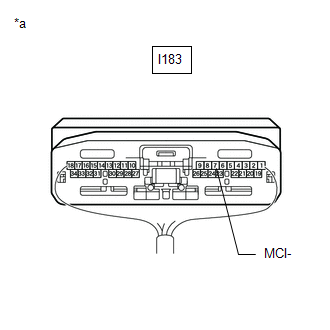
(a) Disconnect the I183 DCM (telematics transceiver) connector.
(b) Disconnect the T21 telephone microphone assembly connector.
(c) Measure the resistance according to the value(s) in the table below.
Standard Resistance:
| Tester Connection | Condition | Specified Condition |
|---|---|---|
| I183-7 (MCI-) - T21-4 (MCO-) | Always | Below 1 Ω |
| I183-7 (MCI-) - Body ground | Always | 10 kΩ or higher |
| NG | | REPAIR OR REPLACE HARNESS OR CONNECTOR |
|
| 4. | CHECK DCM (TELEMATICS TRANSCEIVER) (MCI-) |
| (a) Remove the DCM (telematics transceiver) with the connector(s) still connected. Click here |
|
(b) Measure the resistance according to the value(s) in the table below.
Standard Resistance:
| Tester Connection | Condition | Specified Condition |
|---|---|---|
| I183-7 (MCI-) - Body ground | Always | Below 1 Ω |
| NG | | REPLACE DCM (TELEMATICS TRANSCEIVER) |
|
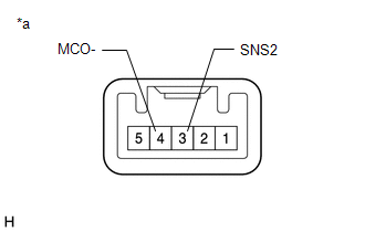
| 5. | INSPECT TELEPHONE MICROPHONE ASSEMBLY (SNS2, MCO-) |
| (a) Remove the telephone microphone assembly. Click here |
|

(b) Measure the resistance according to the value(s) in the table below.
Standard Resistance:
| Tester Connection | Condition | Specified Condition |
|---|---|---|
| 3 (SNS2) - 4 (MCO-) | Always | Below 1 Ω |
| OK | | REPLACE RADIO RECEIVER ASSEMBLY |
| NG | | REPLACE TELEPHONE MICROPHONE ASSEMBLY |
| 6. | CHECK HARNESS AND CONNECTOR (RADIO RECEIVER ASSEMBLY - TELEPHONE MICROPHONE ASSEMBLY) |
(a) Disconnect the I152 radio receiver assembly connector.
(b) Disconnect the T21 telephone microphone assembly connector.
(c) Measure the resistance according to the value(s) in the table below.
Standard Resistance:
| Tester Connection | Condition | Specified Condition |
|---|---|---|
| I152-25 (SNS2) - T21-3 (SNS2) | Always | Below 1 Ω |
| I152-22 (MIN-) - T21-4 (MCO-) | Always | Below 1 Ω |
| I152-25 (SNS2) - Body ground | Always | 10 kΩ or higher |
| I152-22 (MIN-) - Body ground | Always | 10 kΩ or higher |
| NG | | REPAIR OR REPLACE HARNESS OR CONNECTOR |
|
| 7. | INSPECT TELEPHONE MICROPHONE ASSEMBLY (SNS2, MCO-) |
| (a) Remove the telephone microphone assembly. Click here |
|
(b) Measure the resistance according to the value(s) in the table below.
Standard Resistance:
| Tester Connection | Condition | Specified Condition |
|---|---|---|
| 3 (SNS2) - 4 (MCO-) | Always | Below 1 Ω |
| OK | | REPLACE RADIO RECEIVER ASSEMBLY |
| NG | | REPLACE TELEPHONE MICROPHONE ASSEMBLY |
READ NEXT:
 USB Device Malfunction (B1585)
DESCRIPTION This DTC is stored when a malfunction occurs in a connected device. DTC No. Detection Item DTC Detection Condition Trouble Area B1585 USB Device Malfunction When one of th
AV Signal Stoppage (Low Battery Voltage) (B158F)
DESCRIPTION This DTC is stored when a video or audio signal is interrupted due to auxiliary battery voltage input to the radio receiver assembly dropping temporarily. DTC No. Detection Item DTC
Stereo Component Amplifier Malfunction (B15A3)
DESCRIPTION These DTCs are stored when a malfunction occurs in the stereo component amplifier assembly. DTC No. Detection Item DTC Detection Condition Trouble Area B15A3 Stereo Componen
SEE MORE:
Generator Position Sensor Angle Malfunction (P1CAC-200,P1CAF-792,P1CB2-793)
DESCRIPTION The MG ECU, which is built into the inverter with converter assembly, monitors its internal operation and detects the following malfunctions. DTC No. Detection Item DTC Detection Condition Trouble Area MIL Warning Indicate P1CAC-200 Generator Position Sensor Angle Malf
Removal
REMOVAL PROCEDURE 1. DISABLE AUTOAWAY/RETURN FUNCTION (for Power Tilt and Power Telescopic Steering Column) (a) Disable the autoaway/return function by changing the customize parameter. Click here CAUTION: Record the current customize parameter setting (whether the autoaway/return function is enab
