Lexus NX: Generator Position Sensor Angle Malfunction (P1CAC-200,P1CAF-792,P1CB2-793)
DESCRIPTION
The MG ECU, which is built into the inverter with converter assembly, monitors its internal operation and detects the following malfunctions.
| DTC No. | Detection Item | DTC Detection Condition | Trouble Area | MIL | Warning Indicate |
|---|---|---|---|---|---|
| P1CAC-200 | Generator Position Sensor Angle Malfunction | Generator resolver angle malfunction: The difference between the resolver angle for control and estimated resolver angle exceeds the allowable limit. (1 trip detection logic) |
| Comes on | Master Warning Light: Comes on |
| P1CAF-792 | Generator Position Sensor REF Signal Cycle Malfunction | Resolver REF signal cycle malfunction: Excitation signal (REF signal) for resolver angle detection cycle malfunction. (1 trip detection logic) |
| Comes on | Master Warning Light: Comes on |
| P1CB2-793 | Generator Position Sensor REF Signal Stop Malfunction | Resolver REF signal oscillation stop malfunction: An error is detected when the excitation signal (REF signal) for resolver angle detection is not detected. (1 trip detection logic) |
| Comes on | Master Warning Light: Comes on |
| DTC No. | Data List |
|---|---|
| P1CAC-200 | Generator (MG1) Rev |
| P1CAF-792 | |
| P1CB2-793 |
MONITOR DESCRIPTION
The MG ECU performs many diagnostic tests to verify proper operation of internal systems. In one of these tests, the MG ECU checks for an R/D (Resolver/Digital Converter) malfunction involving the generator resolver. If the MG ECU detects an R/D error, it will conclude that there is an internal malfunction involving the generator resolver and the hybrid vehicle control ECU will illuminate the MIL and store a DTC.
MONITOR STRATEGY
| Related DTCs | P1CAC (INF 200): R/D converter resolver angle abnormality P1CAF (INF 792): REF malfunction (frequency abnormality) P1CB2 (INF 793): REF malfunction (REF signal abnormality) |
| Required sensors/components | Inverter with converter assembly (MG ECU) |
| Frequency of operation | Continuous |
| Duration | TMC's intellectual property |
| MIL operation | 1 driving cycle |
| Sequence of operation | None |
TYPICAL ENABLING CONDITIONS
| The monitor will run whenever the following DTCs are not stored | TMC's intellectual property |
| Other conditions belong to TMC's intellectual property | - |
TYPICAL MALFUNCTION THRESHOLDS
| TMC's intellectual property | - |
COMPONENT OPERATING RANGE
| Hybrid vehicle control ECU | DTC P1CAC (INF 200) is not detected DTC P1CAF (INF 792) is not detected DTC P1CB2 (INF 793) is not detected |
CONFIRMATION DRIVING PATTERN
.png)
- Connect the Techstream to the DLC3.
- Turn the power switch on (IG) and turn the Techstream on.
- Clear the DTCs (even if no DTCs are stored, perform the clear DTC procedure).
- Turn the power switch off and wait for 30 seconds or more.
- Turn the power switch on (IG) and wait for 5 seconds or more.
- Turn the power switch on (READY) with the shift lever in P, and wait for 5 seconds or more.
- Depress the accelerator pedal of the vehicle with the engine stopped and the shift lever in P to start the engine.
- Keep the engine running for 5 seconds or more.
- Drive the vehicle forward with the shift lever in D for 5 m (16 ft.) or more. [A]
- Drive the vehicle backward the shift lever in R for 5 m (16 ft.) or more. [B]
- Enter the following menus: Powertrain / Hybrid Control / Trouble Codes. [C]
-
Read the current DTCs.
HINT:
- If a current DTC is output, the system is malfunctioning.
- If current DTCs are not output, check for permanent DTCs.
- Check that the permanent DTCs are cleared.
- If the permanent DTCs are not cleared, perform the universal trip, and then check for permanent DTCs again.
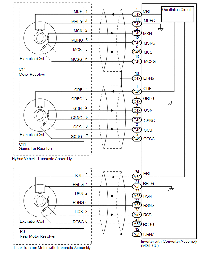
WIRING DIAGRAM
CAUTION / NOTICE / HINT
CAUTION:
- Before inspecting the high-voltage system or disconnecting the low voltage connector of the inverter with converter assembly, take safety precautions such as wearing insulated gloves and removing the service plug grip to prevent electrical shocks. After removing the service plug grip, put it in your pocket to prevent other technicians from accidentally reconnecting it while you are working on the high-voltage system.
-
After removing the service plug grip, wait for at least 10 minutes before touching any of the high-voltage connectors or terminals. After waiting for 10 minutes, check the voltage at the terminals in the inspection point in the inverter with converter assembly. The voltage should be 0 V before beginning work.
Click here
.gif)
HINT:
Waiting for at least 10 minutes is required to discharge the high-voltage capacitor inside the inverter with converter assembly.
NOTICE:
After turning the power switch off, waiting time may be required before disconnecting the cable from the negative (-) auxiliary battery terminal. Therefore, make sure to read the disconnecting the cable from the negative (-) auxiliary battery terminal notices before proceeding with work.
Click here
HINT:
After the repair, clear the DTCs and perform the following procedure to check that DTCs are not output.
- Turn the power switch on (IG) and wait for 5 seconds or more.*
- Turn the power switch on (READY) with the shift lever in P and wait for 5 seconds or more.
- Depress the accelerator pedal of the vehicle with the engine stopped and the shift lever in P to start the engine.
- Keep the engine running for 5 seconds or more.
- Drive the vehicle forward with the shift lever in D for 5 m (16 ft.) or more.
- Drive the vehicle backward with the shift lever in R for 5 m (16 ft.) or more.
-
*: Lightly wiggle the connectors and wire harnesses up and down and right and left.
NOTICE:
If excessive pressure is applied while the connectors and wire harnesses are wiggled, they may be damaged. After the inspection, make sure to return the wire harnesses and clamps to their original position.
PROCEDURE
| 1. | CHECK DTC OUTPUT (HYBRID CONTROL) |
(a) Connect the Techstream to the DLC3.
(b) Turn the power switch on (IG).
(c) Enter the following menus: Powertrain / Hybrid Control / Trouble Codes.
(d) Check for DTCs.
Powertrain > Hybrid Control > Trouble Codes| Result | Proceed to |
|---|---|
| P1CAC-200, P1CAF-792 or P1CB2-793 only is output, or DTCs except the ones in the table below are also output. | A |
| Any of the following DTCs are also output. | B |
| Relevant DTC | |
|---|---|
| P0A3F-243 | Drive Motor "A" Position Sensor Circuit |
| P0A45-669 | Drive Motor "B" Position Sensor Circuit |
| P0A4B-253 | Generator Position Sensor Circuit |
| P0A4C-513 | Generator Position Sensor Circuit Range / Performance |
| P0A4D-255 | Generator Position Sensor Circuit Low |
(e) Turn the power switch off.
| B | .gif) | GO TO DTC CHART (HYBRID CONTROL SYSTEM) |
|
.gif)
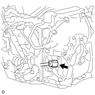
| 2. | CHECK CONNECTOR CONNECTION CONDITION (INVERTER WITH CONVERTER ASSEMBLY CONNECTOR) |
Click here
| Result | Proceed to |
|---|---|
| OK | A |
| NG (The connector is not connected securely.) | B |
| NG (The terminals are not making secure contact or are deformed, or water or foreign matter exists in the connector.) | C |
| B | | CONNECT SECURELY |
| C | | REPAIR OR REPLACE HARNESS OR CONNECTOR |
|
| 3. | CHECK HARNESS AND CONNECTOR (INVERTER WITH CONVERTER ASSEMBLY - GENERATOR RESOLVER) |
CAUTION:
Be sure to wear insulated gloves.
(a) Check that the service plug grip is not installed.
NOTICE:
After removing the service plug grip, do not turn the power switch on (READY), unless instructed by the repair manual because this may cause a malfunction.
(b) Disconnect the C49 inverter with converter assembly connector.
(c) Connect the cable to the negative (-) auxiliary battery terminal.
(d) Turn the power switch on (IG).
| (e) Measure the voltage according to the value(s) in the table below. Standard Voltage:
NOTICE: Turning the power switch on (IG) with the inverter with converter assembly disconnected causes other DTCs to be stored. Clear the DTCs after performing this inspection. |
|

(f) Turn the power switch off.
(g) Disconnect the cable from the negative (-) auxiliary battery terminal.
(h) Reconnect the C49 inverter with converter assembly connector.
| NG | | REPAIR OR REPLACE HARNESS OR CONNECTOR |
|
| 4. | CHECK GENERATOR RESOLVER |
CAUTION:
Be sure to wear insulated gloves.
(a) Check that the service plug grip is not installed.
NOTICE:
After removing the service plug grip, do not turn the power switch on (READY), unless instructed by the repair manual because this may cause a malfunction.
(b) Disconnect the C49 inverter with converter assembly connector.
| (c) Measure the resistance according to the value(s) in the table below. Standard Resistance (Check for Open):
Standard Resistance (Check for Short):
|
|
(d) Reconnect the C49 inverter with converter assembly connector.
| NG | | GO TO STEP 12 |
|
| 5. | CHECK HARNESS AND CONNECTOR (INVERTER WITH CONVERTER ASSEMBLY - MOTOR RESOLVER) |
CAUTION:
Be sure to wear insulated gloves.
(a) Check that the service plug grip is not installed.
NOTICE:
After removing the service plug grip, do not turn the power switch on (READY), unless instructed by the repair manual because this may cause a malfunction.
(b) Disconnect the C49 inverter with converter assembly connector.
(c) Connect the cable to the negative (-) auxiliary battery terminal.
(d) Turn the power switch on (IG).
| (e) Measure the voltage according to the value(s) in the table below. Standard Voltage:
NOTICE: Turning the power switch on (IG) with the inverter with converter assembly disconnected causes other DTCs to be stored. Clear the DTCs after performing this inspection. |
|
(f) Turn the power switch off.
(g) Disconnect the cable from the negative (-) auxiliary battery terminal.
(h) Reconnect the C49 inverter with converter assembly connector.
| NG | | REPAIR OR REPLACE HARNESS OR CONNECTOR |
|
| 6. | CHECK MOTOR RESOLVER |
CAUTION:
Be sure to wear insulated gloves.
(a) Check that the service plug grip is not installed.
NOTICE:
After removing the service plug grip, do not turn the power switch on (READY), unless instructed by the repair manual because this may cause a malfunction.
(b) Disconnect the C49 inverter with converter assembly connector.
| (c) Measure the resistance according to the value(s) in the table below. Standard Resistance (Check for Open):
Standard Resistance (Check for Short):
|
|

(d) Reconnect the C49 inverter with converter assembly connector.
| NG | | GO TO STEP 14 |
|
| 7. | CHECK HARNESS AND CONNECTOR (INVERTER WITH CONVERTER ASSEMBLY - REAR MOTOR RESOLVER) |
CAUTION:
Be sure to wear insulated gloves.
(a) Check that the service plug grip is not installed.
NOTICE:
After removing the service plug grip, do not turn the power switch on (READY), unless instructed by the repair manual because this may cause a malfunction.
(b) Disconnect the A58 inverter with converter assembly connector.
(c) Connect the cable to the negative (-) auxiliary battery terminal.
(d) Turn the power switch on (IG).
| (e) Measure the voltage according to the value(s) in the table below. Standard Voltage:
NOTICE: Turning the power switch on (IG) with the low voltage connector of the inverter with converter assembly disconnected causes other DTCs to be stored. Clear the DTCs after performing this inspection. |
|

(f) Turn the power switch off.
(g) Disconnect the cable from the negative (-) auxiliary battery terminal.
(h) Reconnect the A58 inverter with converter assembly connector.
| NG | | REPAIR OR REPLACE HARNESS OR CONNECTOR |
|
| 8. | CHECK REAR MOTOR RESOLVER |
CAUTION:
Be sure to wear insulated gloves.
(a) Check that the service plug grip is not installed.
NOTICE:
After removing the service plug grip, do not turn the power switch on (READY), unless instructed by the repair manual because this may cause a malfunction.
(b) Disconnect the A58 inverter with converter assembly connector.
| (c) Measure the resistance according to the value(s) in the table below. Standard Resistance (Check for Open):
Standard Resistance (Check for Short):
|
|
(d) Connect the A58 inverter with converter assembly connector.
| NG | | GO TO STEP 16 |
|
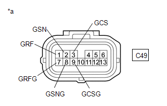
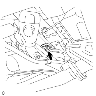
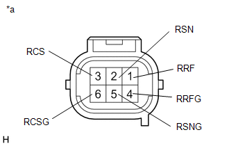
| 9. | CHECK CONNECTOR CONNECTION CONDITION (GENERATOR RESOLVER CONNECTOR) |
| (a) Check the connection condition of the generator resolver connector and the contact pressure of each terminal. Check the terminals for deformation, and check the connector for water ingress and foreign matter. Click here OK: - The connector is connected securely. - The terminals are not deformed and are connected securely. - No water or foreign matter in the connector. |
|
.png)
| Result | Proceed to |
|---|---|
| OK | A |
| NG (The connector is not connected securely.) | B |
| NG (The terminals are not making secure contact or are deformed, or water or foreign matter exists in the connector.) | C |
| B | | CONNECT SECURELY |
| C | | REPAIR OR REPLACE HARNESS OR CONNECTOR |
|
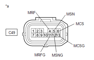
| 10. | CHECK CONNECTOR CONNECTION CONDITION (MOTOR RESOLVER CONNECTOR) |
| (a) Check the connection condition of the motor resolver connector and the contact pressure of each terminal. Check the terminals for deformation, and check the connector for water ingress and foreign matter. Click here OK: - The connector is connected securely. - The terminals are not deformed and are connected securely. - No water or foreign matter in the connector. |
|
| Result | Proceed to |
|---|---|
| OK | A |
| NG (The connector is not connected securely.) | B |
| NG (The terminals are not making secure contact or are deformed, or water or foreign matter exists in the connector.) | C |
| B | | CONNECT SECURELY |
| C | | REPAIR OR REPLACE HARNESS OR CONNECTOR |
|
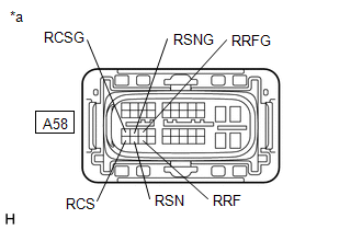
| 11. | CHECK CONNECTOR CONNECTION CONDITION (REAR MOTOR RESOLVER CONNECTOR) |
| (a) Check the connection condition of the rear motor resolver connector and the contact pressure of each terminal. Check the terminals for deformation, and check the connector for water ingress and foreign matter. Click here OK: - The connector is connected securely. - The terminals are not deformed and are connected securely. - No water or foreign matter in the connector. |
|
| Result | Proceed to |
|---|---|
| OK | A |
| NG (The connector is not connected securely.) | B |
| NG (The terminals are not making secure contact or are deformed, or water or foreign matter exists in the connector.) | C |
| A | | REPLACE INVERTER WITH CONVERTER ASSEMBLY |
| B | | CONNECT SECURELY |
| C | | REPAIR OR REPLACE HARNESS OR CONNECTOR |
| 12. | CHECK CONNECTOR CONNECTION CONDITION (GENERATOR RESOLVER CONNECTOR) |
| (a) Check the connection condition of the generator resolver connector and the contact pressure of each terminal. Check the terminals for deformation, and check the connector for water ingress and foreign matter. Click here OK: - The connector is connected securely. - The terminals are not deformed and are connected securely. - No water or foreign matter in the connector. |
|
| Result | Proceed to |
|---|---|
| OK | A |
| NG (The connector is not connected securely.) | B |
| NG (The terminals are not making secure contact or are deformed, or water or foreign matter exists in the connector.) | C |
| B | | CONNECT SECURELY |
| C | | REPAIR OR REPLACE HARNESS OR CONNECTOR |
|
| 13. | INSPECT HYBRID VEHICLE TRANSAXLE ASSEMBLY (GENERATOR RESOLVER) |
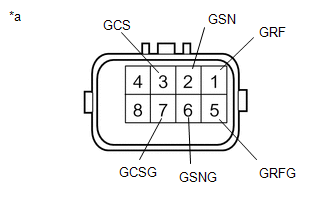
(a) Disconnect the C41 generator resolver connector.
| (b) Measure the resistance according to the value(s) in the table below. Standard Resistance:
Standard Resistance (Check for Short):
HINT: The generator resolver is not available as a supply part. If it requires replacement, replace the hybrid vehicle transaxle assembly. |
|
(c) Reconnect the C41 generator resolver connector.
| OK | | REPAIR OR REPLACE HARNESS OR CONNECTOR |
| NG | | REPLACE HYBRID VEHICLE TRANSAXLE ASSEMBLY |
| 14. | CHECK CONNECTOR CONNECTION CONDITION (MOTOR RESOLVER CONNECTOR) |
| (a) Check the connection condition of the motor resolver connector and the contact pressure of each terminal. Check the terminals for deformation, and check the connector for water ingress and foreign matter. Click here OK: - The connector is connected securely. - The terminals are not deformed and are connected securely. - No water or foreign matter in the connector. |
|
| Result | Proceed to |
|---|---|
| OK | A |
| NG (The connector is not connected securely.) | B |
| NG (The terminals are not making secure contact or are deformed, or water or foreign matter exists in the connector.) | C |
| B | | CONNECT SECURELY |
| C | | REPAIR OR REPLACE HARNESS OR CONNECTOR |
|
| 15. | INSPECT HYBRID VEHICLE TRANSAXLE ASSEMBLY (MOTOR RESOLVER) |
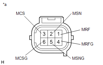
(a) Disconnect the C44 motor resolver connector.
| (b) Measure the resistance according to the value(s) in the table below. Standard Resistance (Check for Open):
Standard Resistance (Check for Short):
HINT: The motor resolver is not available as a supply part. If it requires replacement, replace the hybrid vehicle transaxle assembly. |
|
(c) Reconnect the C44 motor resolver connector.
| OK | | REPAIR OR REPLACE HARNESS OR CONNECTOR |
| NG | | REPLACE HYBRID VEHICLE TRANSAXLE ASSEMBLY |
| 16. | CHECK CONNECTOR CONNECTION CONDITION (REAR MOTOR RESOLVER CONNECTOR) |
| (a) Check the connection condition of the rear motor resolver connector and the contact pressure of each terminal. Check the terminals for deformation, and check the connector for water ingress and foreign matter. Click here OK: - The connector is connected securely. - The terminals are not deformed and are connected securely. - No water or foreign matter in the connector. |
|
| Result | Proceed to |
|---|---|
| OK | A |
| NG (The connector is not connected securely.) | B |
| NG (The terminals are not making secure contact or are deformed, or water or foreign matter exists in the connector.) | C |
| B | | CONNECT SECURELY |
| C | | REPAIR OR REPLACE HARNESS OR CONNECTOR |
|
| 17. | INSPECT REAR TRACTION MOTOR WITH TRANSAXLE ASSEMBLY (REAR MOTOR RESOLVER) |
(a) Disconnect the R3 rear motor resolver connector.
| (b) Measure the resistance according to the value(s) in the table below. Standard Resistance (Check for Open):
Standard Resistance (Check for Short):
HINT: The rear motor resolver is not available as a supply part. If it requires replacement, replace the rear traction motor with transaxle assembly. |
|
(c) Reconnect the R3 rear motor resolver connector.
| OK | | REPAIR OR REPLACE HARNESS OR CONNECTOR |
| NG | | REPLACE REAR TRACTION MOTOR WITH TRANSAXLE ASSEMBLY |
READ NEXT:
 Drive Motor "A" Position Sensor Angle Malfunction (P1CAD-168,P1CB0-795,P1CB3-796)
DESCRIPTION The MG ECU, which is built into the inverter with converter assembly, monitors its internal operation and detects malfunctions. HINT: The term "drive motor A" indicates the motor (MG2).
Drive Motor "B" Position Sensor Angle Malfunction (P1CAE-715,P1CB1-798,P1CB4-799)
DESCRIPTION The inverter with converter assembly (MG ECU) monitors its internal operation and detects malfunctions. DTC No. Detection Item DTC Detection Condition Trouble Area MIL Warning
Throttle / Pedal Position Sensor / Switch "D" Circuit (P2120-152,...,P2138-154)
DESCRIPTION The accelerator pedal position sensor is mounted on the accelerator pedal to detect how much the pedal is depressed. This is a non-contact sensor with Hall elements. There are 2 outputs fr
SEE MORE:
Components
COMPONENTS ILLUSTRATION *1 DECK BOARD ASSEMBLY *2 NO. 2 DECK BOARD SUB-ASSEMBLY *3 NO. 3 DECK BOARD SUB-ASSEMBLY *4 TONNEAU COVER ASSEMBLY ILLUSTRATION *1 DECK FLOOR BOX LH *2 DECK FLOOR BOX RH *3 NO. 1 TOOL BOX SUB-ASSEMBLY *4 NO. 2 TOOL BOX SUB-ASSEMBLY
Removal
REMOVAL PROCEDURE 1. REMOVE NO. 2 FORWARD RECOGNITION COVER Click here 2. REMOVE NO. 1 FORWARD RECOGNITION COVER Click here 3. REMOVE PROTECTOR (a) Detach the 2 claws and remove the protector. 4. REMOVE AIR CONDITIONING THERMISTOR ASSEMBLY (HUMIDITY SENSOR) (a) Disconnect the connector. (
