Lexus NX: Voltage Inverter
Components
COMPONENTS
ILLUSTRATION
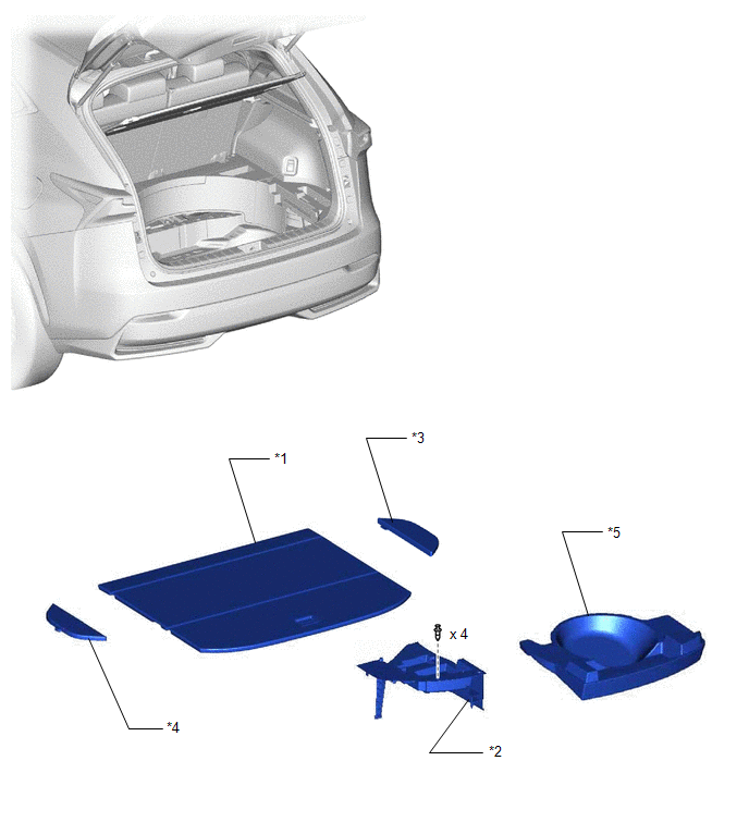
| *1 | DECK BOARD ASSEMBLY | *2 | DECK FLOOR BOX LH |
| *3 | NO. 2 DECK BOARD SUB-ASSEMBLY | *4 | NO. 3 DECK BOARD SUB-ASSEMBLY |
| *5 | REAR DECK FLOOR BOX | - | - |
ILLUSTRATION
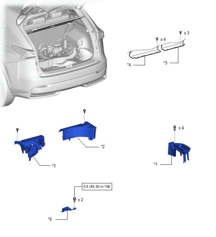
| *1 | DECK FLOOR BOX RH | *2 | NO. 1 TOOL BOX SUB-ASSEMBLY |
| *3 | NO. 2 TOOL BOX SUB-ASSEMBLY | *4 | REAR SEAT BACK BOARD CARPET ASSEMBLY LH |
| *5 | REAR SEAT BACK BOARD CARPET ASSEMBLY RH | *6 | VOLTAGE INVERTER ASSEMBLY |
.png) | N*m (kgf*cm, ft.*lbf): Specified torque | - | - |
On-vehicle Inspection
ON-VEHICLE INSPECTION
PROCEDURE
1. INSPECT VOLTAGE INVERTER ASSEMBLY
(a) Measure the voltage and resistance of each terminal from the back of the wire harness connector with the connector connected.

Standard:
| Tester Connection | Input/Output | Item | Condition | Specified Condition |
|---|---|---|---|---|
| 1(IG) - 4(GND) | Input | Voltage | Engine switch on (IG) | 11 to 14 V |
| 3(AC1) - 7(AC2) *1 | Output | Voltage | Inverter operating with engine switch on (IG) | 75 to 120 V *2 |
| 4(GND) - Body ground | - | Resistance | Always | Below 1 Ω |
| 7(AC2) - 3(AC1) *1 | Output | Voltage | Inverter operating with engine switch on (IG) | 75 to 120 V *2 |
HINT:
- *1: When measuring with the tester, AC voltage is generated. Therefore, make sure to set the tester to the AC voltage range.
- *2: Since the AC voltage cannot be exactly measured with the tester, a wide range has been listed for the specified condition.
If the result is not as specified, replace the voltage inverter assembly.
READ NEXT:
 Wireless Charger Assembly
ComponentsCOMPONENTS ILLUSTRATION *1 MOBILE WIRELESS CHARGER CRADLE ASSEMBLY - - RemovalREMOVAL PROCEDURE 1. REMOVE MOBILE WIRELESS CHARGER CRADLE ASSEMBLY (a) Remove the 5 screws.
Parts Location
PARTS LOCATION ILLUSTRATION *1 MOBILE WIRELESS CHARGER CRADLE ASSEMBLY *2 CERTIFICATION ECU (SMART KEY ECU ASSEMBLY) *3 INSTRUMENT PANEL JUNCTION BLOCK ASSEMBLY - ACC FUSE - PANEL FUSE
SEE MORE:
Parts Location
PARTS LOCATION ILLUSTRATION *1 NO. 1 ENGINE ROOM RELAY BLOCK AND JUNCTION BLOCK ASSEMBLY - AM2 FUSE *2 NO. 2 ENGINE ROOM RELAY BLOCK AND JUNCTION BLOCK ASSEMBLY - ECU-B NO.1 FUSE ILLUSTRATION *1 WIRELESS DOOR LOCK BUZZER *2 DOOR CONTROL RECEIVER *3 FRONT DOOR OUTSIDE HAN
On-vehicle Inspection
ON-VEHICLE INSPECTION CAUTION / NOTICE / HINT CAUTION: Be sure to follow the correct removal and installation procedures of the front airbag sensors. PROCEDURE 1. INSPECT FRONT AIRBAG SENSOR (for Vehicle not Involved in Collision) (a) Perform a diagnostic system check. Click here 2. INSPECT FRONT
