Lexus NX: Wireless Charger Assembly
Components
COMPONENTS
ILLUSTRATION
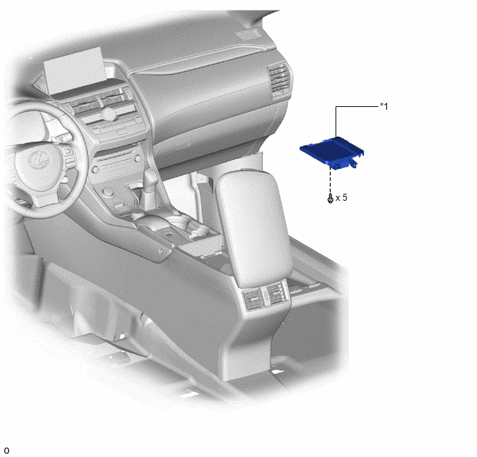
| *1 | MOBILE WIRELESS CHARGER CRADLE ASSEMBLY | - | - |
Removal
REMOVAL
PROCEDURE
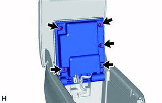
1. REMOVE MOBILE WIRELESS CHARGER CRADLE ASSEMBLY
| (a) Remove the 5 screws. |
|
| (b) Detach the clamp. |
|
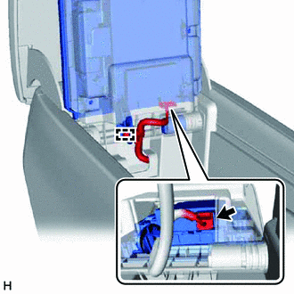
(c) Disconnect the connector.
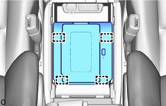
| (d) Detach the 4 guides and remove the mobile wireless charger cradle assembly. |
|
Installation
INSTALLATION
PROCEDURE
1. INSTALL MOBILE WIRELESS CHARGER CRADLE ASSEMBLY
| (a) Attach the 4 guides. |
|
.png)
| (b) Connect the connector. |
|
.png)
(c) Attach the clamp.
| (d) Install the mobile wireless charger cradle assembly with the 5 screws. |
|
.png)
READ NEXT:
 Parts Location
PARTS LOCATION ILLUSTRATION *1 MOBILE WIRELESS CHARGER CRADLE ASSEMBLY *2 CERTIFICATION ECU (SMART KEY ECU ASSEMBLY) *3 INSTRUMENT PANEL JUNCTION BLOCK ASSEMBLY - ACC FUSE - PANEL FUSE
Precaution
PRECAUTION HANDLING PRECAUTIONS (a) For safety, when driving the vehicle, the driver should not operate a portable device that is charging. (b) Anyone using an implanted pacemaker, biventricular pacin
SEE MORE:
Hybrid Battery Pack State of Charge High (P0C30-390)
DESCRIPTION The hybrid vehicle control ECU monitors its internal operation and will store a DTC and perform fail-safe control if it detects the following malfunction. DTC No. Detection Item DTC Detection Condition Trouble Area MIL Warning Indicate P0C30-390 Hybrid Battery Pack Sta
Inspection
INSPECTION PROCEDURE 1. INSPECT OUTER REAR VIEW MIRROR ASSEMBLY LH (a) Check the operation of the mirror surface. (1) Disconnect the outer rear view mirror assembly LH connector. *a Component without harness connected (Outer Rear View Mirror Assembly LH) (2) Apply auxiliar
© 2016-2026 Copyright www.lexunx.com
