Lexus NX: Adjustment
ADJUSTMENT
PROCEDURE
1. INSPECT SHIFT LEVER POSITION
(a) While moving the shift lever from N to each position, check that the lever moves smoothly and that the shift position indicator comes on properly according to the shift lever position.
(b) Put the vehicle into the READY-on state and check the following:
(1) When the shift lever is moved to D, the vehicle moves forward.
(2) When the shift lever is moved to R, the vehicle moves in reverse.
NOTICE:
The vehicle should not move when the shift position indicator is off.
2. REMOVE NO. 1 SPEAKER WITH BOX ASSEMBLY (w/ ASC System)
Click here .gif)
3. REMOVE REAR CONSOLE BOX ASSEMBLY (w/o ASC System)
Click here
4. ADJUST SHIFT LEVER POSITION
(a) Move the shift lever to N.
| (b) Slide the slider of the transmission control cable assembly in the direction indicated by the arrow and pull the lock piece outward. |
|
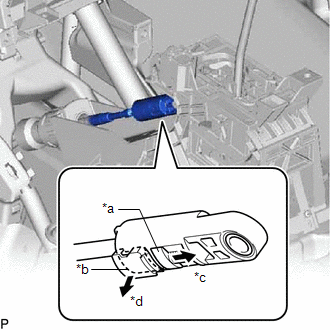
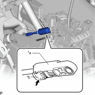
(c) Gently lift the cable rod with your fingers to pull the cable tight.
| (d) Push the lock piece into the adjuster case. NOTICE:
|
|
(e) After adjusting the shift lever position, check the operation and function of the shift lever. If there is a problem, adjust the position again.
5. INSTALL REAR CONSOLE BOX ASSEMBLY (w/o ASC System)
Click here
6. INSTALL NO. 1 SPEAKER WITH BOX ASSEMBLY (w/ ASC System)
Click here
READ NEXT:
 Installation
INSTALLATION PROCEDURE 1. INSTALL TRANSMISSION CONTROL CABLE ASSEMBLY NOTICE: Before installing the transmission control cable assembly, check that the shift lever position sensor and the shift lever
SEE MORE:
Drive Motor "B" Control Module (P0A1C-713)
DESCRIPTION The MG ECU, which is built into the inverter with converter assembly, monitors its internal operation and will store DTCs if the system is malfunctioning. If any of the following DTCs are output, replace the inverter with converter assembly. DTC No. Detection Item DTC Detection Co
Refueling
Opening the fuel tank cap
Before refueling the vehicle
Turn the power switch off and
ensure that all the doors and windows
are closed.
Confirm the type of fuel.
■Fuel tank opening for unleaded gasoline
To help prevent incorrect fueling, your vehicle
has a fuel tank opening that onl
