.gif)
.png)
- Power switch off
- Electrical key transmitter sub-assembly brought outside vehicle
- All doors closed
- Back door opener switch assembly off → on
Lexus NX: Back Door Entry Lock and Unlock Functions do not Operate
Lexus NX Service Manual / Vehicle Interior / Theft Deterrent / Keyless Entry / Smart Access System With Push-button Start (for Entry Function) / Back Door Entry Lock and Unlock Functions do not Operate
DESCRIPTION
If the entry lock and unlock functions do not operate for the back door only, the request code may not be being transmitted from the back door. If the entry functions for other doors operate properly, communication between the electrical key transmitter sub-assembly and door control receiver assembly is normal. In this case, there may be a problem with request code transmission (communication between the certification ECU (smart key ECU assembly) and electrical key antenna (outside luggage compartment)), or there may be electric wave interference.
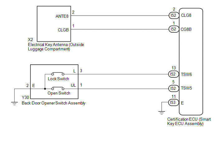
WIRING DIAGRAM
CAUTION / NOTICE / HINT
NOTICE:
-
The smart access system with push-button start (for Entry Function) uses the LIN communication system and CAN communication system. Inspect the communication function by following How to Proceed with Troubleshooting. Troubleshoot the smart access system with push-button start (for Entry Function) after confirming that the communication systems are functioning properly.
Click here
.gif)
- When using the Techstream with the power switch off, connect the Techstream to the DLC3 and turn a courtesy light switch on and off at intervals of 1.5 seconds or less until communication between the Techstream and the vehicle begins. Then select the vehicle type under manual mode and enter the following menus: Body Electrical / Smart Access. While using the Techstream, periodically turn a courtesy light switch on and off at intervals of 1.5 seconds or less to maintain communication between the Techstream and the vehicle.
- Check that there are no electrical key transmitter sub-assemblies in the vehicle.
-
Before replacing the certification ECU (smart key ECU assembly), refer to smart access system with push-button start (for Entry Function) Precaution.
Click here
- After repair, confirm that no DTCs are output by performing "DTC Output Confirmation Operation".
PROCEDURE
| 1. | CHECK POWER DOOR LOCK CONTROL SYSTEM |
(a) When the door control switch on the multiplex network master switch assembly is operated, check that the doors unlock and lock according to the switch operation.
Click here
OK:
Door locks operate normally.
| NG | .gif) | GO TO POWER DOOR LOCK CONTROL SYSTEM |
|
| 2. | CHECK FOR DTC |
(a) Check for DTCs.
Body Electrical > Smart Access > Trouble Codes| Result | Proceed to |
|---|---|
| DTC B27A8 is not output | A |
| DTC B27A8 is output | B |
| B | | GO TO OTHER DIAGNOSTIC TROUBLE CODE CHART |
|
| 3. | CHECK WAVE ENVIRONMENT |
| (a) Bring the electrical key transmitter sub-assembly approximately 0.3 m (0.984 ft.) from the electrical key antenna (outside luggage compartment) and perform an entry back door open/lock function check. Click here
|
|
| Result | Proceed to |
|---|---|
| Entry function does not operate normally | A |
| Entry function operates normally | B |
| B | | AFFECTED BY WAVE INTERFERENCE |
|
| 4. | READ VALUE USING TECHSTREAM (TR/B DOOR LOCK SW, TR/B DOOR UNLOCK SW) |
(a) Connect the Techstream to the DLC3.
(b) Turn the power switch on (IG).
(c) Turn the Techstream on.
(d) Enter the following menus: Body Electrical / Smart Access / Data List.
(e) Read the Data List according to the display on the Techstream.
Body Electrical > Smart Access > Data List| Tester Display | Measurement Item | Range | Normal Condition | Diagnostic Note |
|---|---|---|---|---|
| Tr/B-Door Lock SW | Back door opener switch assembly (lock switch) | ON or OFF | ON: Back door opener switch assembly (lock switch) pressed OFF: Back door opener switch assembly (lock switch) not pressed |
|
| Tr/B-Door Unlock SW | Back door opener switch assembly (open switch) | ON or OFF | ON: Back door opener switch assembly (open switch) pressed OFF: Back door opener switch assembly (open switch) not pressed |
|
| Tester Display |
|---|
| Tr/B-Door Lock SW |
| Tr/B-Door Unlock SW |
OK:
The Techstream display changes correctly in response to the operation of the back door opener switch assembly.
| NG | | GO TO STEP 9 |
|
| 5. | CHECK KEY DIAGNOSTIC MODE |
(a) Check the following antenna in key diagnostic mode.
Body Electrical > Smart Access > Utility| Tester Display |
|---|
| Communication Check(Key Diag Mode) |
| (b) Select either channel 1 or channel 2 and perform the key diagnostic mode inspection for each channel. (1) Check the electrical key antenna (outside luggage compartment): When the electrical key transmitter sub-assembly is brought within 0.7 to 1 m (2.30 to 3.28 ft.) of the electrical key antenna (outside luggage compartment), check that the wireless buzzer sounds. HINT:
|
|
| Result | Proceed to |
|---|---|
| Wireless buzzer does not sound | A |
| Wireless buzzer sounds | B |
| B | | REPLACE CERTIFICATION ECU (SMART KEY ECU ASSEMBLY) |
|
| 6. | CHECK HARNESS AND CONNECTOR (ELECTRICAL KEY ANTENNA (OUTSIDE LUGGAGE COMPARTMENT) - CERTIFICATION ECU (SMART KEY ECU ASSEMBLY)) |
(a) Disconnect the X2 electrical key antenna (outside luggage compartment) connector.
(b) Disconnect the I52 certification ECU (smart key ECU assembly) connector.
(c) Measure the resistance according to the value(s) in the table below.
Standard Resistance:
| Tester Connection | Condition | Specified Condition |
|---|---|---|
| X2-2 (ANTE8) - I52-2 (CLG8) | Always | Below 1 Ω |
| X2-1 (CLGB) - I52-1 (CG8B) | Always | Below 1 Ω |
| X2-2 (ANTE8) or I52-2 (CLG8) - Body ground | Always | 10 kΩ or higher |
| X2-1 (CLGB) or I52-1 (CG8B) - Body ground | Always | 10 kΩ or higher |
(d) Connect the I52 certification ECU (smart key ECU assembly) connector.
(e) Disconnect the X2 electrical key antenna (outside luggage compartment) connector.
| NG | | REPAIR OR REPLACE HARNESS OR CONNECTOR |
|
| 7. | INSPECT CERTIFICATION ECU (SMART KEY ECU ASSEMBLY) (OUTPUT TO ELECTRICAL KEY ANTENNA (OUTSIDE LUGGAGE COMPARTMENT)) |
(a) Using an oscilloscope, check the waveform.
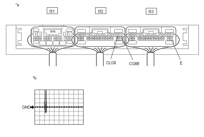
| *a | Component with harness connected (Certification ECU (Smart Key ECU Assembly)) | *b | Waveform 1 |
OK:
| Tester Connection | Condition | Tool Setting | Specified Condition |
|---|---|---|---|
| I52-2 (CLG8) - I53-11 (E) | Procedure: | 2 V/DIV., 500 ms/DIV. | Pulse generation (See waveform 1) |
| I52-1 (CG8B) - I53-11 (E) | Procedure:
| 2 V/DIV., 500 ms/DIV. | Pulse generation (See waveform 1) |
| OK | | REPLACE ELECTRICAL KEY ANTENNA (OUTSIDE LUGGAGE COMPARTMENT) |
|
| 8. | CHECK ENTRY LOCK OPERATION |
(a) Connect all connectors and check that the entry lock and unlock functions operate.
Click here
| Result | Proceed to |
|---|---|
| Entry function does not operate normally | A |
| Entry function operates normally | B |
| A | | REPLACE CERTIFICATION ECU (SMART KEY ECU ASSEMBLY) |
| B | | END (CONNECTOR WAS NOT CONNECTED SECURELY) |
| 9. | CHECK HARNESS AND CONNECTOR (BACK DOOR OPENER SWITCH ASSEMBLY - CERTIFICATION ECU (SMART KEY ECU ASSEMBLY) AND BODY GROUND) |
(a) Disconnect the Y30 back door opener switch assembly connector.
(b) Disconnect the I52 certification ECU (smart key ECU assembly) connector.
(c) Measure the resistance according to the value(s) in the table below.
Standard Resistance:
| Tester Connection | Condition | Specified Condition |
|---|---|---|
| Y30-3 (L) - I52-13 (TSW6) | Always | Below 1 Ω |
| Y30-1 (UL) - I52-5 (TSW5) | Always | Below 1 Ω |
| Y30-2 (E) - Body ground | Always | Below 1 Ω |
| Y30-3 (L) or I52-13 (TSW6) - Body ground | Always | 10 kΩ or higher |
| Y30-1 (UL) or I52-5 (TSW5) - Body ground | Always | 10 kΩ or higher |
| NG | | REPAIR OR REPLACE HARNESS OR CONNECTOR |
|
| 10. | INSPECT BACK DOOR OPENER SWITCH ASSEMBLY |
(a) Remove the back door opener switch assembly.
Click here
(b) Inspect the back door opener switch assembly.
Click here
| NG | | REPLACE BACK DOOR OPENER SWITCH ASSEMBLY |
|
| 11. | CHECK ENTRY LOCK OPERATION |
(a) Connect all connectors and check that the entry lock and unlock functions operate.
Click here
| Result | Proceed to |
|---|---|
| Entry function does not operate normally | A |
| Entry function operates normally | B |
| A | | REPLACE CERTIFICATION ECU (SMART KEY ECU ASSEMBLY) |
| B | | END (CONNECTOR WAS NOT CONNECTED SECURELY) |
READ NEXT:
 Back Door Entry Lock Function does not Operate
DESCRIPTION If the entry lock function does not operate for the back door only, but the entry unlock function operates, the request code is being transmitted properly from the back door. In this case,
New Key cannot be Registered
DESCRIPTION If an electrical key transmitter sub-assembly could not be newly registered, wave interference or a malfunction of the certification ECU (smart key ECU assembly), electrical key transmitte
Additional Key cannot be Registered
DESCRIPTION If additional registration is not possible, a malfunction in the electrical key transmitter sub-assembly, certification ECU (smart key ECU assembly), power switch, No. 2 indoor electrical
SEE MORE:
Glass Temperature Sensor Circuit (B14A8)
DESCRIPTION The air conditioning amplifier assembly detects the windshield glass surface temperature from this circuit. The air conditioning amplifier assembly applies voltage to the air conditioning thermistor assembly (glass temperature sensor). As the windshield glass surface temperature rises, t
Components
COMPONENTS ILLUSTRATION *1 DECK FLOOR BOX LH *2 NO. 3 DECK BOARD SUB-ASSEMBLY *3 REAR DECK FLOOR BOX *4 AUXILIARY BATTERY NEGATIVE TERMINAL N*m (kgf*cm, ft.*lbf): Specified torque - - ILLUSTRATION *1 COWL SIDE TRIM BOARD LH *2 DOOR SCUFF PLATE ASSEMBLY LH
© 2016-2026 Copyright www.lexunx.com
