Lexus NX: Back Door Entry Lock Function does not Operate
DESCRIPTION
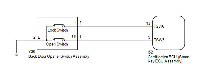
If the entry lock function does not operate for the back door only, but the entry unlock function operates, the request code is being transmitted properly from the back door. In this case, there may be a problem related to the lock switch (connection between the back door opener switch assembly and certification ECU (smart key ECU assembly)).
WIRING DIAGRAM
CAUTION / NOTICE / HINT
NOTICE:
-
The smart access system with push-button start (for Entry Function) uses the LIN communication system and CAN communication system. Inspect the communication function by following How to Proceed with Troubleshooting. Troubleshoot the smart access system with push-button start (for Entry Function) after confirming that the communication systems are functioning properly.
Click here
.gif)
- When using the Techstream with the power switch off, connect the Techstream to the DLC3 and turn a courtesy light switch on and off at intervals of 1.5 seconds or less until communication between the Techstream and the vehicle begins. Then select the vehicle type under manual mode and enter the following menus: Body Electrical / Smart Access. While using the Techstream, periodically turn a courtesy light switch on and off at intervals of 1.5 seconds or less to maintain communication between the Techstream and the vehicle.
- Check that there are no electrical key transmitter sub-assemblies in the vehicle.
-
Before replacing the certification ECU (smart key ECU assembly), refer to smart access system with push-button start (for Entry Function) Precaution.
Click here
- After repair, confirm that no DTCs are output by performing "DTC Output Confirmation Operation".
PROCEDURE
| 1. | CHECK POWER DOOR LOCK CONTROL SYSTEM |
(a) When the door control switch on the multiplex network master switch assembly is operated, check that the doors unlock and lock according to the switch operation.
Click here
OK:
Door locks operate normally.
| NG | .gif) | GO TO POWER DOOR LOCK CONTROL SYSTEM |
|
.gif)
| 2. | INSPECT TECHSTREAM (TR/B-DOOR LOCK SW) |
(a) Connect the Techstream to the DLC3.
(b) Turn the power switch on (IG).
(c) Turn the Techstream on.
(d) Enter the following menus: Body Electrical / Smart Access / Data List.
(e) Read the Data List according to the display on the Techstream.
Body Electrical > Smart Access > Data List| Tester Display | Measurement Item | Range | Normal Condition | Diagnostic Note |
|---|---|---|---|---|
| Tr/B-Door Lock SW | Back door opener switch assembly (lock switch) | ON or OFF | ON: Back door opener switch assembly (lock switch) pressed OFF: Back door opener switch assembly (lock switch) not pressed |
|
| Tester Display |
|---|
| Tr/B-Door Lock SW |
HINT:
When checking the operation of the entry lock function several times, it can be operated up to 2 times consecutively. To operate the function 3 times or more consecutively, the doors need to be unlocked once. However, this is only for the entry lock function, other door lock operations, such as a wireless door lock operation can be performed consecutively.
OK:
The Techstream display changes correctly in response to the operation of the back door opener switch assembly.
| OK | | REPLACE CERTIFICATION ECU (SMART KEY ECU ASSEMBLY) |
|
| 3. | CHECK HARNESS AND CONNECTOR (BACK DOOR OPENER SWITCH ASSEMBLY - CERTIFICATION ECU (SMART KEY ECU ASSEMBLY)) |
(a) Disconnect the Y30 back door opener switch assembly connector.
(b) Disconnect the I52 certification ECU (smart key ECU assembly) connector.
(c) Measure the resistance according to the value(s) in the table below.
Standard Resistance:
| Tester Connection | Condition | Specified Condition |
|---|---|---|
| Y30-3 (L) - I52-13 (TSW6) | Always | Below 1 Ω |
| Y30-2 (E) - Body ground | Always | Below 1 Ω |
| Y30-3 (L) or I52-13 (TSW6) - Body ground | Always | 10 kΩ or higher |
| NG | | REPAIR OR REPLACE HARNESS OR CONNECTOR |
|
| 4. | INSPECT BACK DOOR OPENER SWITCH ASSEMBLY (LOCK SWITCH) |
(a) Remove the back door opener switch assembly.
Click here
(b) Inspect the back door opener switch assembly.
Click here
| OK | | REPLACE CERTIFICATION ECU (SMART KEY ECU ASSEMBLY) |
| NG | | REPLACE BACK DOOR OPENER SWITCH ASSEMBLY |
READ NEXT:
 New Key cannot be Registered
DESCRIPTION If an electrical key transmitter sub-assembly could not be newly registered, wave interference or a malfunction of the certification ECU (smart key ECU assembly), electrical key transmitte
Additional Key cannot be Registered
DESCRIPTION If additional registration is not possible, a malfunction in the electrical key transmitter sub-assembly, certification ECU (smart key ECU assembly), power switch, No. 2 indoor electrical
Entry Unlock and Unlatch Functions do not Operate Using Kick Sensor
DESCRIPTION If the hands free power back door operation does not operate, it could indicate the certification ECU (smart key ECU assembly) did not transmit a power back door open request signal, or a
SEE MORE:
IG Power Source Circuit
DESCRIPTION When the power switch is turned on (IG), the IG power source circuit supplies positive (+) voltage to the multiplex tilt and telescopic ECU. The multiplex tilt and telescopic ECU also receives power switch signals via this circuit. WIRING DIAGRAM CAUTION / NOTICE / HINT NOTICE: Inspect
How To Proceed With Troubleshooting
CAUTION / NOTICE / HINT HINT:
Use the following procedure to troubleshoot the seat heater system.
*: Use the Techstream.
PROCEDURE 1. VEHICLE BROUGHT TO WORKSHOP
NEXT 2. CUSTOMER PROBLEM ANALYSIS HINT:
In troubleshooting, confirm that the problem symptom
