Lexus NX: Components
Lexus NX Service Manual / Vehicle Interior / Heating / Air Conditioning / Air Conditioning Panel / Components
COMPONENTS
ILLUSTRATION
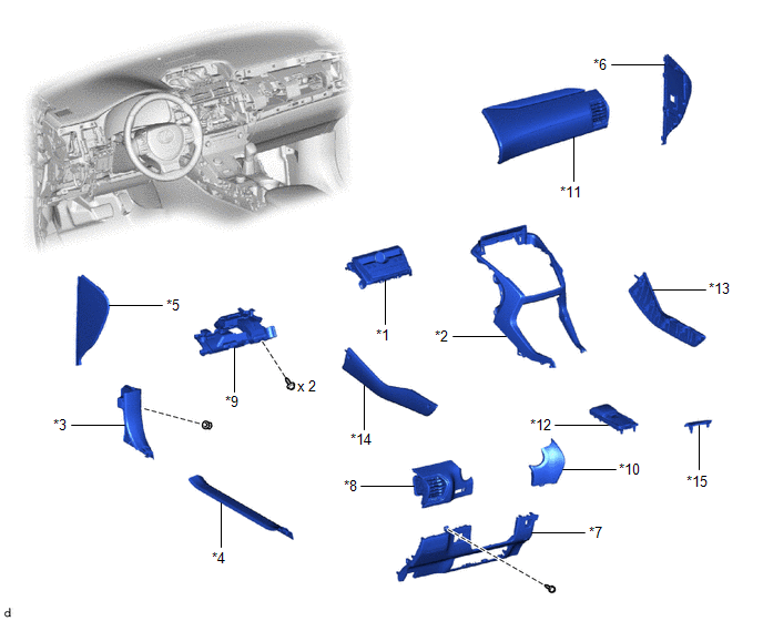
| *1 | AIR CONDITIONING CONTROL ASSEMBLY | *2 | CENTER INSTRUMENT CLUSTER FINISH PANEL ASSEMBLY |
| *3 | COWL SIDE TRIM BOARD LH | *4 | DOOR SCUFF PLATE ASSEMBLY LH |
| *5 | INSTRUMENT SIDE PANEL LH | *6 | INSTRUMENT SIDE PANEL RH |
| *7 | LOWER NO. 1 INSTRUMENT PANEL FINISH PANEL | *8 | NO. 1 INSTRUMENT PANEL SAFETY PAD SUB-ASSEMBLY |
| *9 | NO. 1 INSTRUMENT PANEL UNDER COVER SUB-ASSEMBLY | *10 | NO. 1 SWITCH HOLE BASE |
| *11 | NO. 2 INSTRUMENT PANEL SAFETY PAD SUB-ASSEMBLY | *12 | REAR CONSOLE ARMREST ASSEMBLY |
| *13 | UPPER NO. 1 CONSOLE PANEL GARNISH | *14 | UPPER NO. 2 CONSOLE PANEL GARNISH |
| *15 | UPPER REAR CONSOLE PANEL | - | - |
READ NEXT:
 Removal
REMOVAL PROCEDURE 1. REMOVE MULTI-DISPLAY ASSEMBLY Click here 2. REMOVE DOOR SCUFF PLATE ASSEMBLY LH Click here 3. REMOVE COWL SIDE TRIM BOARD LH Click here 4. REMOVE REAR CONSOLE ARMREST ASS
Installation
INSTALLATION PROCEDURE 1. INSTALL AIR CONDITIONING CONTROL ASSEMBLY (a) Connect the 2 connectors. (b) Attach the 6 clips to install the air conditioning control assembly. NOTICE: Do not touch the s
SEE MORE:
Inspection
INSPECTION PROCEDURE 1. INSPECT POWER WINDOW REGULATOR MOTOR ASSEMBLY LH NOTICE:
Do not apply voltage to any terminals except terminals 1 and 2 to avoid damaging the pulse sensor inside the motor.
Reset the power window regulator motor (initialize the pulse sensor) after installing the power wi
Mute Signal Circuit between Stereo Component Amplifier and Telematics Transceiver
DESCRIPTION This DCM (telematics transceiver) sends a mute signal to the stereo component amplifier assembly. The stereo component amplifier assembly controls the volume according to the mute signal from the DCM (telematics transceiver). If there is an open in the circuit, noise can be heard from th
© 2016-2026 Copyright www.lexunx.com
