Lexus NX: Blind Spot Monitor Sensor
Removal
REMOVAL
CAUTION / NOTICE / HINT
NOTICE:
- Avoid any impact to the blind spot monitor sensor.
- Do not drop the blind spot monitor sensor. If it is dropped, replace it with a new one.
PROCEDURE
1. REMOVE REAR BUMPER COVER
Click here .gif)
2. REMOVE BLIND SPOT MONITOR SENSOR LH
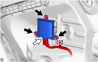
(a) Remove the clamp.
.png) | Nut |
.png) | Connector |
(b) Disconnect the connector.
| (c) Remove the 3 nuts. NOTICE: If the removed nut is the same shape as that shown in the illustration, replace it the supplied replacement part. |
|

(d) Remove the blind spot monitor sensor LH.
3. REMOVE BLIND SPOT MONITOR SENSOR RH
HINT:
Use the same procedure described for the LH side.
Installation
INSTALLATION
CAUTION / NOTICE / HINT
NOTICE:
- Avoid any impact to the blind spot monitor sensor.
- Do not drop the blind spot monitor sensor. If it is dropped, replace it with a new one.
PROCEDURE
1. INSTALL BLIND SPOT MONITOR SENSOR LH
(a) Connect the connector.
(b) Attach the clamp.
(c) Install the blind spot monitor sensor LH with the 3 nuts.
Torque:
10 N·m {102 kgf·cm, 7 ft·lbf}
NOTICE:
If the removed nut is the same shape as that shown in the illustration, replace it with a new nut of supplied replacement part.
.png)
2. INSTALL BLIND SPOT MONITOR SENSOR RH
HINT:
Use the same procedure described for the LH side.
3. PERFORM BLIND SPOT MONITOR INSTALLATION CONDITION INSPECTION
Click here .gif)
4. INSTALL REAR BUMPER COVER
Click here
5. PERFORM BLIND SPOT MONITOR BEAM AXIS INSPECTION
Click here
6. PERFORM BLIND SPOT MONITOR BEAM AXIS CONFIRMATION
Click here
7. PERFORM DIAGNOSTIC SYSTEM CHECK
Click here
READ NEXT:
 Precaution
PRECAUTION PRECAUTIONS FOR BLIND SPOT MONITOR SYSTEM (a) The blind spot monitor function may not detect vehicles correctly in the following conditions: (1) When the sensor is misaligned due to a stron
Parts Location
PARTS LOCATION ILLUSTRATION *A w/ Panoramic View Monitor System *B w/ Parking Assist Monitor System *1 BLIND SPOT MONITOR SENSOR LH (MASTER) *2 BLIND SPOT MONITOR SENSOR RH (SLAVE)
SEE MORE:
Mirror Heater does not Operate with Rear Defogger Switch
DESCRIPTION When therear window defogger switch (mirror heater switch) is operated, a mirror heater signal is sent to the air conditioning amplifier assembly via LIN communication. The air conditioning amplifier assembly sends the signal to the outer mirror control ECU assembly via CAN communication
Problem Symptoms Table
PROBLEM SYMPTOMS TABLE HINT:
Use the table below to help determine the cause of problem symptoms. If multiple suspected areas are listed, the potential causes of the symptoms are listed in order of probability in the "Suspected Area" column of the table. Check each symptom by checking the suspect
