- DTC judgment completed
- System normal
Lexus NX: Camshaft Position Sensor Circuit (P0340,P0342,P0343)
Lexus NX Service Manual / Engine & Hybrid System / 2ar-fxe (engine Control) / Sfi System / Camshaft Position Sensor Circuit (P0340,P0342,P0343)
DESCRIPTION
The camshaft position sensor (VV1 signal) consists of a magnet and MRE (Magneto-Resistive Element).
The camshaft has a timing rotor for the camshaft position sensor. When the camshaft rotates, changes occur in the air gaps between the timing rotor and MRE, which affects the magnetic field. As a result, the resistance of the MRE material fluctuates. The camshaft position sensor converts the camshaft rotation data to pulse signals, uses the pulse signals to determine the camshaft angle, and sends it to the ECM.
Then the ECM uses this data to control fuel injection duration, fuel injection timing and Variable Valve Timing (VVT) system.
| DTC No. | Detection Item | DTC Detection Condition | Trouble Area | MIL | Memory |
|---|---|---|---|---|---|
| P0340 | Camshaft Position Sensor Circuit | Either of the following conditions is met:
|
| Comes on | DTC stored |
| P0342 | Camshaft Position Sensor "A" Circuit Low Input (Bank 1 or Single Sensor) | The output voltage of the camshaft position sensor is less than 0.3 V for 4 seconds (1 trip detection logic). |
| Comes on | DTC stored |
| P0343 | Camshaft Position Sensor "A" Circuit High Input (Bank 1 or Single Sensor) | The output voltage of the camshaft position sensor is higher than 4.7 V for 4 seconds (1 trip detection logic). |
| Comes on | DTC stored |
-
Reference: Inspection using an oscilloscope
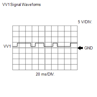
HINT:
- The correct waveform is as shown.
- VV stands for the camshaft position sensor signal.
ECM Terminal Name
Between VV1+ and VV1-
Tester Range
5 V/DIV., 20 ms./DIV.
Condition
Idling with warm engine
MONITOR DESCRIPTION
If no pulse signal is transmitted by the camshaft position sensor despite the camshaft rotating, or if the rotation of the intake camshaft and the crankshaft is not synchronized, the ECM interprets this as a malfunction of the sensor.
Also, when the sensor output voltage remains at less than 0.3 V, or higher than 4.7 V for 4 seconds, the ECM stores a DTC.
MONITOR STRATEGY
| Related DTCs | P0340: Camshaft position sensor verify pulse input P0342: Camshaft position sensor range check (low voltage) P0343: Camshaft position sensor range check (high voltage) |
| Required Sensors/Components (Main) | Camshaft position sensor |
| Required Sensors/Components (Related) | Crankshaft position sensor |
| Frequency of Operation | Continuous |
| Duration | 4 seconds: P0342 (Camshaft position sensor range check [low voltage]) P0343 (Camshaft position sensor range check [high voltage]) 5 seconds: P0340 (Camshaft position sensor verify pulse input) |
| MIL Operation | Immediate |
| Sequence of Operation | None |
TYPICAL ENABLING CONDITIONS
All| Monitor runs whenever the following DTCs are not stored | None |
| All of the following conditions are met | - |
| Engine speed | 600 rpm or higher |
| Starter | Off |
| VVT system mis-alignment | Not detected |
| Camshaft position sensor range check fail (P0342, P0343) | Not detected |
| Lost communication with hybrid vehicle control ECU (U0293) | Not detected |
| Hybrid control module judge | Engine running |
| Camshaft position sensor voltage | 0.3 to 4.7 V |
| All of the following conditions are met | - |
| Starter | Off |
| Power switch | On (IG) |
| Time after power switch off to on (IG) | 2 seconds or more |
| Camshaft position sensor verify pulse input fail (P0340) | Not detected |
| Auxiliary battery voltage | 8 V or higher |
TYPICAL MALFUNCTION THRESHOLDS
P0340: Camshaft Position Sensor Verify Pulse Input| Either of the following conditions is met | 1 or 2 |
| 1. Camshaft position and crankshaft position alignment | Mis-alignment |
| 2. Camshaft position sensor signal | No signal |
| Camshaft position sensor voltage | Less than 0.3 V |
| Camshaft position sensor voltage | Higher than 4.7 V |
COMPONENT OPERATING RANGE
| All of the following conditions are met | - |
| Camshaft position sensor voltage | 0.3 to 4.7 V |
| Camshaft position sensor signal | Signal input |
| Camshaft position and crankshaft position alignment | Aligned |
CONFIRMATION DRIVING PATTERN
- Connect the Techstream to the DLC3.
- Turn the power switch on (IG) and turn the Techstream on.
- Clear the DTCs (even if no DTCs are stored, perform the clear DTC procedure).
- Turn the power switch off and wait for at least 30 seconds.
- Turn the power switch on (IG) and turn the Techstream on.
-
Put the engine in inspection mode (maintenance mode).
Click here
.gif)
- Start the engine.
- Idle the engine for 10 seconds or more [A].
- Enter the following menus: Powertrain / Engine and ECT / Trouble Codes [B].
-
Read the pending DTCs.
HINT:
- If a pending DTC is output, the system is malfunctioning.
- If a pending DTC is not output, perform the following procedure.
- Enter the following menus: Powertrain / Engine and ECT / Utility / All Readiness.
- Input the DTC: P0340, P0342 or P0343.
-
Check the DTC judgment result.
Techstream Display
Description
NORMAL
ABNORMAL
- DTC judgment completed
- System abnormal
INCOMPLETE
- DTC judgment not completed
- Perform driving pattern after confirming DTC enabling conditions
N/A
- Unable to perform DTC judgment
- Number of DTCs which do not fulfill DTC preconditions has reached ECU memory limit
HINT:
- If the judgment result shows NORMAL, the system is normal.
- If the judgment result shows ABNORMAL, the system has a malfunction.
- If the judgment result shows INCOMPLETE or N/A, perform steps [A] and [B] again.
-
If no pending DTC is output, perform a universal trip and check for permanent DTCs.
Click here
HINT:
- If a permanent DTC is output, the system is malfunctioning.
- If no permanent DTC is output, the system is normal.
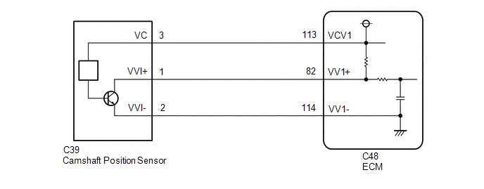
WIRING DIAGRAM
CAUTION / NOTICE / HINT
HINT:
- If no problem is found through this diagnostic troubleshooting procedure, there may be a mechanical problem with the engine.
- Read freeze frame data using the Techstream. The ECM records vehicle and driving condition information as freeze frame data the moment a DTC is stored. When troubleshooting, freeze frame data can help determine if the vehicle was moving or stationary, if the engine was warmed up or not, if the air fuel ratio was lean or rich, and other data from the time the malfunction occurred.
PROCEDURE
| 1. | CHECK TERMINAL VOLTAGE (POWER SOURCE OF CAMSHAFT POSITION SENSOR) |
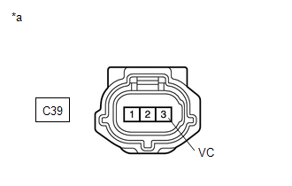
| *a | Front view of wire harness connector (to Camshaft Position Sensor) |
(a) Disconnect the camshaft position sensor connector.
(b) Turn the power switch on (IG).
(c) Measure the voltage according to the value(s) in the table below.
Standard Voltage:
| Tester Connection | Condition | Specified Condition |
|---|---|---|
| C39-3 (VC) - Body ground | Power switch on (IG) | 4.5 to 5.5 V |
| NG | .gif) | GO TO STEP 10 |
|
.gif)
| 2. | CHECK HARNESS AND CONNECTOR (CAMSHAFT POSITION SENSOR - ECM) |
(a) Disconnect the camshaft position sensor connector.
(b) Disconnect the ECM connector.
(c) Measure the resistance according to the value(s) in the table below.
Standard Resistance:
| Tester Connection | Condition | Specified Condition |
|---|---|---|
| C39-1 (VVI+) - C48-82 (VV1+) | Always | Below 1 Ω |
| C39-2 (VVI-) - C48-114 (VV1-) | Always | Below 1 Ω |
| C39-1 (VVI+) or C48-82 (VV1+) - Body ground | Always | 10 kΩ or higher |
| C39-2 (VVI-) or C48-114 (VV1-) - Body ground | Always | 10 kΩ or higher |
| NG | | REPAIR OR REPLACE HARNESS OR CONNECTOR |
|
| 3. | CHECK SENSOR INSTALLATION (CAMSHAFT POSITION SENSOR) |
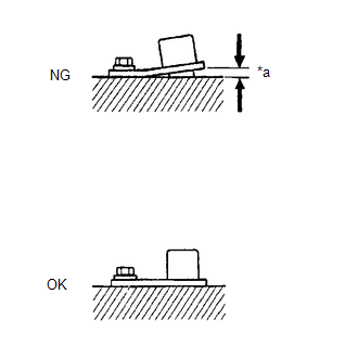
| *a | Clearance |
(a) Check the camshaft position sensor installation.
OK:
Camshaft position sensor is installed correctly.
| NG | | SECURELY REINSTALL CAMSHAFT POSITION SENSOR |
|
| 4. | INSPECT CAMSHAFT (TIMING ROTOR) |
(a) Check the timing rotor of the intake camshaft.
OK:
Camshaft timing rotor does not have any cracks or deformation.
HINT:
Perform "Inspection After Repair" after replacing the camshaft.
Click here
| NG | | REPLACE CAMSHAFT |
|
| 5. | CHECK VALVE TIMING |
Click here
| NG | | GO TO STEP 8 |
|
| 6. | REPLACE CAMSHAFT POSITION SENSOR |
(a) Replace the camshaft position sensor.
Click here
|
| 7. | CHECK WHETHER DTC OUTPUT RECURS (DTC P0340, P0342 OR P0343) |
(a) Connect the Techstream to the DLC3.
(b) Turn the power switch on (IG).
(c) Turn the Techstream on.
(d) Clear the DTCs.
Click here
(e) Turn the power switch off and wait for at least 30 seconds.
(f) Drive the vehicle in accordance with the driving pattern described in the Confirmation Driving Pattern.
(g) Enter the following menus: Powertrain / Engine and ECT / Trouble Codes.
(h) Read the pending DTCs.
Powertrain > Engine and ECT > Trouble Codes| Result | Proceed to |
|---|---|
| DTC P0340, P0342 or P0343 is output | A |
| DTCs are not output | B |
HINT:
If the engine does not start, replace the ECM.
| A | | REPLACE ECM |
| B | | END |
| 8. | CHECK ENGINE MECHANICAL SYSTEM |
(a) Check for mechanical malfunctions that affect the valve timing, such as a jumped tooth or stretching of the timing chain.
| NG | | REPAIR OR REPLACE MALFUNCTIONING PARTS, COMPONENT AND AREA |
|
| 9. | CHECK WHETHER DTC OUTPUT RECURS (DTC P0340, P0342 OR P0343) |
(a) Connect the Techstream to the DLC3.
(b) Turn the power switch on (IG).
(c) Turn the Techstream on.
(d) Clear the DTCs.
Click here
(e) Turn the power switch off and wait for at least 30 seconds.
(f) Drive the vehicle in accordance with the driving pattern described in the Confirmation Driving Pattern.
(g) Enter the following menus: Powertrain / Engine and ECT / Trouble Codes.
(h) Read the pending DTCs.
Powertrain > Engine and ECT > Trouble Codes| Result | Proceed to |
|---|---|
| DTC P0340, P0342 or P0343 is output | A |
| DTCs are not output | B |
HINT:
If the engine does not start, replace the ECM.
| A | | REPLACE ECM |
| B | | CHECK FOR INTERMITTENT PROBLEMS |
| 10. | CHECK HARNESS AND CONNECTOR (CAMSHAFT POSITION SENSOR - ECM) |
(a) Disconnect the camshaft position sensor connector.
(b) Disconnect the ECM connector.
(c) Measure the resistance according to the value(s) in the table below.
Standard Resistance:
| Tester Connection | Condition | Specified Condition |
|---|---|---|
| C39-3 (VC) - C48-113 (VCV1) | Always | Below 1 Ω |
| C39-3 (VC) or C48-113 (VCV1) - Body ground | Always | 10 kΩ or higher |
| OK | | REPLACE ECM |
| NG | | REPAIR OR REPLACE HARNESS OR CONNECTOR |
READ NEXT:
 Ignition Coil "A" Primary / Secondary Circuit (P0351-P0354)
DESCRIPTION HINT:
These DTCs indicate malfunctions relating to the primary circuit.
If DTC P0351 is output, check the No. 1 ignition coil assembly (No. 1 cylinder) circuit.
If DTC P0352 is outp
Exhaust Gas Recirculation Flow Insufficient Detected (P0401)
DESCRIPTION Based on the driving conditions, the ECM regulates the volume of exhaust gas that is recirculated to the engine's combustion chambers and thus lowers the combustion temperature to reduce N
Exhaust Gas Recirculation Control Circuit (P0403)
DESCRIPTION Refer to DTC P0401. Click here DTC No. Detection Item DTC Detection Condition Trouble Area MIL Memory P0403 Exhaust Gas Recirculation Control Circuit Both of the fo
SEE MORE:
Blind Spot Monitor Slave Module Beam Axis Inspection Incomplete (C1ABC)
DESCRIPTION This DTC is stored when a beam axis inspection has not been performed for the blind spot monitor sensor RH. HINT: This DTC is always stored after replacing a blind spot monitor sensor. The purpose of this DTC is to ensure that beam axis inspection is performed. Completing the beam axis i
Installation
INSTALLATION CAUTION / NOTICE / HINT HINT:
Use the same procedure for the RH and LH sides.
The procedure listed below is for the LH side.
PROCEDURE 1. INSTALL OUTER MIRROR CONTROL ECU ASSEMBLY (a) Install the outer mirror control ECU assembly with the 2 screws. (b) Connect the 2 connectors.
© 2016-2026 Copyright www.lexunx.com
