Lexus NX: Parts Location
PARTS LOCATION
ILLUSTRATION
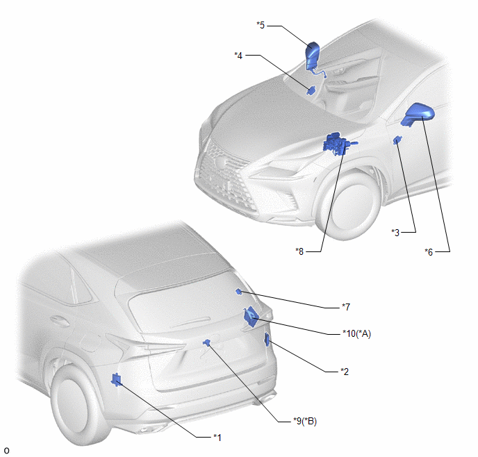
| *A | w/ Panoramic View Monitor System | *B | w/ Parking Assist Monitor System |
| *1 | BLIND SPOT MONITOR SENSOR LH (MASTER) | *2 | BLIND SPOT MONITOR SENSOR RH (SLAVE) |
| *3 | OUTER MIRROR CONTROL ECU ASSEMBLY LH | *4 | OUTER MIRROR CONTROL ECU ASSEMBLY RH |
| *5 | OUTER REAR VIEW MIRROR ASSEMBLY RH - OUTER MIRROR RH (OUTER REAR VIEW MIRROR INDICATOR RH) - OUTER MIRROR RETRACTOR RH | *6 | OUTER REAR VIEW MIRROR ASSEMBLY LH - OUTER MIRROR LH (OUTER REAR VIEW MIRROR INDICATOR LH) - OUTER MIRROR RETRACTOR LH |
| *7 | RCTA BUZZER (BLIND SPOT MONITOR BUZZER) | *8 | BRAKE BOOSTER WITH MASTER CYLINDER (SKID CONTROL ECU) |
| *9 | REAR TELEVISION CAMERA ASSEMBLY | *10 | PARKING ASSIST ECU |
ILLUSTRATION
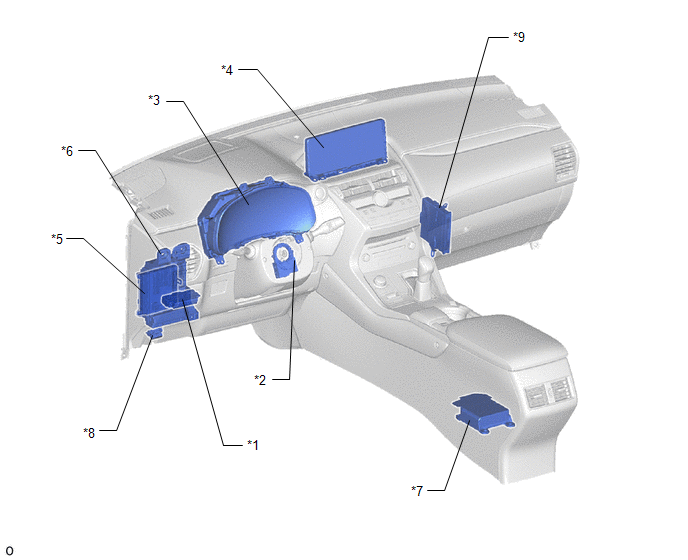
| *1 | BLIND SPOT MONITOR MAIN SWITCH (COMBINATION SWITCH ASSEMBLY) | *2 | STEERING SENSOR |
| *3 | COMBINATION METER ASSEMBLY | *4 | MULTI-DISPLAY ASSEMBLY |
| *5 | MAIN BODY ECU (MULTIPLEX NETWORK BODY ECU) | *6 | INSTRUMENT PANEL JUNCTION BLOCK ASSEMBLY - ECU-IG NO.1 FUSE - ECU-IG NO.2 FUSE |
| *7 | AIRBAG ECU ASSEMBLY | *8 | DLC3 |
| *9 | HYBRID VEHICLE CONTROL ECU | - | - |
READ NEXT:
 System Diagram
SYSTEM DIAGRAM
System Description
SYSTEM DESCRIPTION CAN COMMUNICATION SYSTEM (a) The blind spot monitor system uses CAN communication to transmit data between the right and left blind spot monitor sensors and each ECU. (b) If there i
How To Proceed With Troubleshooting
CAUTION / NOTICE / HINT HINT:
Use the following procedure to troubleshoot the blind spot monitor system.
*: Use the Techstream.
PROCEDURE 1. VEHICLE BROUGHT TO WORKSHOP
NEXT
SEE MORE:
Installation
INSTALLATION PROCEDURE 1. INSTALL FUEL LID WITH MOTOR LOCK ASSEMBLY (a) Connect the connector. (b) Install the fuel lid with motor lock assembly. 2. INSTALL FUEL FILLER OPENING LID LOCK RETAINER (a) Install the fuel filler opening lid lock retainer as shown in the illustration. 3. INS
Removal
REMOVAL CAUTION / NOTICE / HINT CAUTION: Wear protective gloves. Sharp areas on the parts may injure your hands. PROCEDURE 1. REMOVE FRONT SEAT ASSEMBLY LH Click here 2. REMOVE FRONT LOWER SEAT CUSHION SHIELD Click here 3. REMOVE FRONT SEAT CUSHION SHIELD LH Click here 4. REMOVE FRONT INNER S
