Lexus NX: Brake Line
Precaution
PRECAUTION
NOTICE:
- Since the brake lines are classified as critical safety related parts, be sure to disassemble and inspect the components if any brake fluid leaks are found. If any abnormality is found, replace the component with a new one.
- When removing brake system components, cover the brake line connections to prevent foreign matter such as dust or dirt from entering the lines.
- Do not allow brake fluid to adhere to any painted surface such as the vehicle body. If brake fluid leaks onto any painted surface, immediately clean it off.
- When installing a brake tube grommet to the body, ensure that the brake line passes through the center of the grommet.
- Do not damage or deform the brake lines when removing and installing them.
- When installing a brake line or flexible hose, ensure that they are free from twists or bends.
- Do not deform the bracket and body when connecting a brake line and flexible hose.
- If the cap of a flexible hose does not match the groove on the bracket, twist the hose slightly to insert it.
- Flexible hoses must be free from shock absorber oil, grease, etc.
- When installing a brake line to a plastic clamp, ensure that the brake line is not loose or pinched.
- Do not reuse any clips or plastic clamps removed from a flexible hose.
- After installing a brake line or flexible hose, ensure that they do not interfere with any other components.
-
When disconnecting and connecting a flexible hose and brake line:
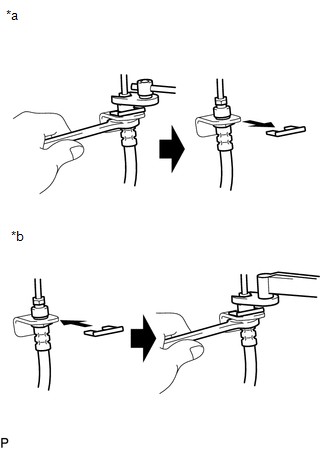
*a
Disconnecting
*b
Connecting
- Hold the flexible hose with a wrench and disconnect the brake line with a union nut wrench without deforming the line.
- Remove the clip.
- Install a new clip.
- Connect the brake line with a union nut wrench without deforming the line.
-
When connecting a brake line and way:
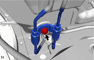
- Support the way to prevent deformation of the brake line and connect the brake line to the way with a union nut wrench.
- Support the way to prevent deformation of the brake line and install the bolt to secure the way to the body.
System Diagram
SYSTEM DIAGRAM
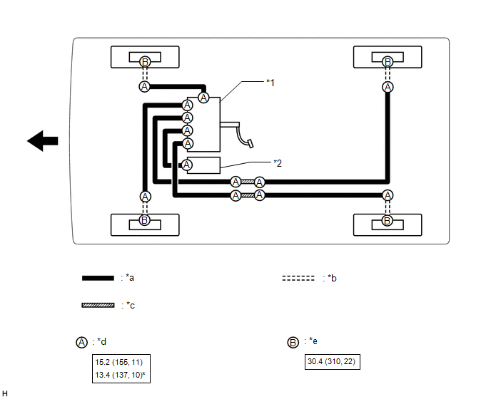
| *1 | Brake Booster with Master Cylinder Assembly | *2 | Brake Booster Pump Assembly |
| *a | Brake Line | *b | Flexible Hose |
| *c | Brake Tube Way | *d | Union Nut |
| *e | Union Bolt | - | - |
.png) | N*m (kgf*cm, ft.*lbf): Specified torque | * | For use with a union nut wrench |
.png) | Front | - | - |
READ NEXT:
 Components
COMPONENTS ILLUSTRATION *1 DECK FLOOR BOX LH *2 NO. 3 DECK BOARD SUB-ASSEMBLY *3 REAR DECK FLOOR BOX *4 NEGATIVE AUXILIARY BATTERY TERMINAL N*m (kgf*cm, ft.*lbf): Specified
Removal
REMOVAL PROCEDURE 1. PRECAUTION CAUTION: Be sure to read Precoution thoroughly before serving. Click here NOTICE: After turning the power switch off, there may be a waiting time before disconnecting
SEE MORE:
Driving the vehicle
The specified procedures should be
observed to ensure safe driving:
Driving procedure
■ Starting the hybrid system
■ Driving
1. With the brake pedal depressed,
shift the shift lever to D.
2. Release the parking brake.
If the parking brake is in automatic mode,
the parking brake is rele
Headlight Cleaner Motor and Relay Circuit
DESCRIPTION The headlight ECU sub-assembly RH controls the headlight cleaner motor and pump assembly. WIRING DIAGRAM CAUTION / NOTICE / HINT NOTICE:
First check that the front washer operates normally.
Inspect the fuses for circuits related to this system before performing the following inspec
© 2016-2026 Copyright www.lexunx.com
