Lexus NX: Removal
REMOVAL
PROCEDURE
1. PRECAUTION
CAUTION:
Be sure to read Precoution thoroughly before serving.
Click here .gif)
NOTICE:
After turning the power switch off, there may be a waiting time before disconnecting the negative (-) auxiliary battery terminal.
Click here
2. REMOVE NO. 3 DECK BOARD SUB-ASSEMBLY
Click here
3. REMOVE REAR DECK FLOOR BOX
Click here
4. REMOVE DECK FLOOR BOX LH
Click here
5. DISCONNECT NEGATIVE AUXILIARY BATTERY TERMINAL
CAUTION:
- Wait at least 90 seconds after disconnecting the cable from the negative (-) auxiliary battery terminal to disable the SRS system.
- If the airbag deploys for any reason. it may cause a serious accident.
(a) Loosen the nut and disconnect the negative (-) auxiliary battery terminal.
6. REMOVE LOWER NO. 1 INSTRUMENT PANEL AIRBAG ASSEMBLY
Click here
7. REMOVE UPPER INSTRUMENT PANEL SUB-ASSEMBLY
Click here
8. REMOVE STOP LIGHT SWITCH ASSEMBLY
Click here
9. REMOVE BRAKE PEDAL RETURN SPRING
(a) Remove the brake pedal return spring from the brake pedal support assembly.
10. REMOVE PUSH ROD PIN
(a) Remove the clip from the push rod pin.
(b) Remove the push rod pin from the push rod clevis.
11. REMOVE BRAKE PEDAL SUPPORT ASSEMBLY
| (a) Remove the brake pedal support reinforcement set bolt. |
|
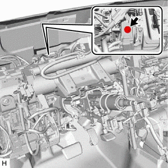
| (b) Disconnect the connector from the brake pedal stroke sensor assembly. |
|
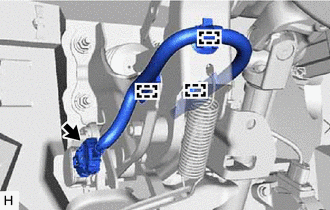
(c) Disconnect the 3 clamps from the brake pedal support assembly.
(d) Remove the 4 nuts and brake pedal support assembly.
12. REMOVE BRAKE PEDAL STROKE SENSOR ASSEMBLY
Click here
13. REMOVE BRAKE PEDAL PAD
(a) Remove the brake pedal pad from the brake pedal support assembly.
READ NEXT:
 Adjustment
ADJUSTMENT PROCEDURE 1. INSPECT AND ADJUST BRAKE PEDAL HEIGHT (a) Check the brake pedal height. *1 Brake Pedal Pad - - *a Brake Pedal Height *b Measuring Plane of Floor Panel Br
Installation
INSTALLATION PROCEDURE 1. INSTALL BRAKE PEDAL PAD (a) Install the brake pedal pad to the brake pedal support assembly. 2. INSTALL BRAKE PEDAL STROKE SENSOR ASSEMBLY Click here 3. INSTALL BRAKE PEDAL
SEE MORE:
Satellite Radio Broadcast cannot be Received
WIRING DIAGRAM CAUTION / NOTICE / HINT NOTICE:
Some satellite radio broadcasts require payment. A contract must be made between a satellite radio company and the user. If the contract expires, it will not be possible to listen to the broadcast.
When replacing the radio receiver assembly, alway
Installation
INSTALLATION PROCEDURE 1. INSTALL NO. 4 ANTENNA CORD SUB-ASSEMBLY (a) Attach the 2 clamps and guide to install the No. 4 antenna cord sub-assembly. (b) Install the bolt and attach the 2 clamps to install the washer hose. (c) Connect each connector. 2. INSTALL NO. 2 ANTENNA CORD SUB-ASSEMBLY (a) When
