Lexus NX: Relay
On-vehicle Inspection
ON-VEHICLE INSPECTION
PROCEDURE
1. INSPECT POWER OUTLET SOCKET RELAY
| (a) Remove the power outlet socket relay. |
|
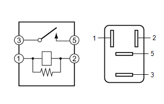
(b) Measure the resistance according to the value(s) in the table below.
Standard Resistance:
| Tester Connection | Condition | Specified Condition |
|---|---|---|
| 3 - 5 | Battery voltage not applied to terminals 1 and 2 | 10 kΩ or higher |
| 3 - 5 | Battery voltage applied to terminals 1 and 2 | Below 1 Ω |
If the result is not as specified, replace the power outlet socket relay.
READ NEXT:
 Voltage Inverter
ComponentsCOMPONENTS ILLUSTRATION *1 DECK BOARD ASSEMBLY *2 DECK FLOOR BOX LH *3 NO. 2 DECK BOARD SUB-ASSEMBLY *4 NO. 3 DECK BOARD SUB-ASSEMBLY *5 REAR DECK FLOOR BOX -
Wireless Charger Assembly
ComponentsCOMPONENTS ILLUSTRATION *1 MOBILE WIRELESS CHARGER CRADLE ASSEMBLY - - RemovalREMOVAL PROCEDURE 1. REMOVE MOBILE WIRELESS CHARGER CRADLE ASSEMBLY (a) Remove the 5 screws.
SEE MORE:
Extension Module Disconnected 2 (B1543)
DESCRIPTION If the radio receiver assembly cannot detect the navigation ECU for a certain period of time (90 seconds) after the power switch is turned on (ACC) and the radio receiver assembly confirms that the information is missing by checking past navigation ECU recognition information (registered
Data List / Active Test
DATA LIST / ACTIVE TEST DATA LIST HINT: Using the Techstream to read the Data List allows the values or states of switches, sensors, actuators and other items to be read without removing any parts. This non-intrusive inspection can be very useful because intermittent conditions or signals may be dis
© 2016-2026 Copyright www.lexunx.com
