Lexus NX: Calibration
CALIBRATION
SELECT COMPASS DISPLAY MODE (w/ Compass)
(a) The compass switch allows selection of the compass display.
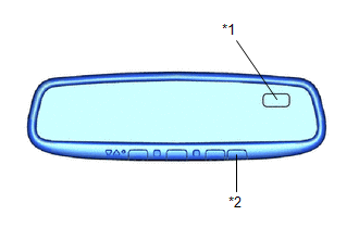
| *1 | Compass Display |
| *2 | Compass Switch |
PERFORM CALIBRATION (w/ Compass)
(a) The compass indicates the direction that the vehicle is heading by detecting the direction and strength of the earth's magnetic field (magnetic north).
(b) Because each vehicle has its own magnetic field, calibration should be performed. The calibration function is used to compensate for the residual magnetism of the vehicle.
WHEN COMPASS IS MAGNETIZED (w/ Compass)
(a) The compass or vehicle may become magnetized while the vehicle is being shipped. As a result, it is necessary to perform calibration for the compass before the vehicle is delivered to the customer. If calibration cannot be performed successfully (calibration cannot be completed despite driving in calibration mode several times), it may be caused by excessive magnetization of the vehicle. Demagnetize the vehicle using a demagnetizer and perform calibration again.
SET COMPASS (w/ Compass)
CALIBRATION MODE (w/ Compass)
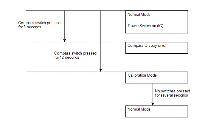
(a) When the compass is in normal mode, pressing the compass switch for 12 seconds will activate calibration mode.
(b) Drive the vehicle in a circle at a speed of 8 km/h (5 mph) or less.
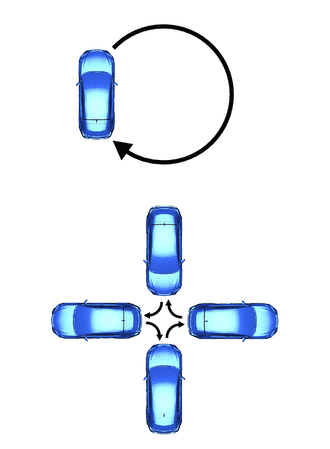
(c) After driving in a circle 1 to 3 times, the direction (N, NE, E, SE, S, SW, W or NW) will be displayed on the compass display. This indicates that calibration has finished.
HINT:
After calibration is performed, it is not necessary to repeat the calibration procedure unless the magnetic field of the vehicle changes drastically. If the magnetic field changes drastically, the compass display will indicate "C".
READ NEXT:
 Problem Symptoms Table
PROBLEM SYMPTOMS TABLE HINT: Use the table below to help determine the cause of problem symptoms. If multiple suspected areas are listed, the potential causes of the symptoms are listed in order of pr
Removal
REMOVAL PROCEDURE 1. REMOVE NO. 2 FORWARD RECOGNITION COVER Click here 2. REMOVE NO. 1 FORWARD RECOGNITION COVER Click here 3. REMOVE INNER REAR VIEW MIRROR ASSEMBLY (a) Disconnect the connec
Inspection
INSPECTION PROCEDURE 1. INSPECT INNER REAR VIEW MIRROR ASSEMBLY (a) Inspect the operation of the electrochromic inner rear view mirror assembly. (1) Connect a positive (+) lead from the battery to ter
SEE MORE:
Installation
INSTALLATION CAUTION / NOTICE / HINT HINT:
Use the same procedure for RHD and LHD vehicles.
The procedures listed below are for LHD vehicles.
PROCEDURE 1. INSTALL LOWER NO. 1 INSTRUMENT PANEL AIRBAG ASSEMBLY (a) Check that the power switch is off. (b) Check that the cable is disconnected fro
Short to GND in Outer Mirror Indicator(Master) (C1AB2)
DESCRIPTION This DTC is stored when the blind spot monitor sensor LH detects a ground short in the outer rear view mirror indicator LH. DTC No. Detection Item DTC Detection Condition Trouble Area Note C1AB2 Short to GND in Outer Mirror Indicator(Master) Both of the following cond
