Lexus NX: Camera Heater
Components
COMPONENTS
ILLUSTRATION
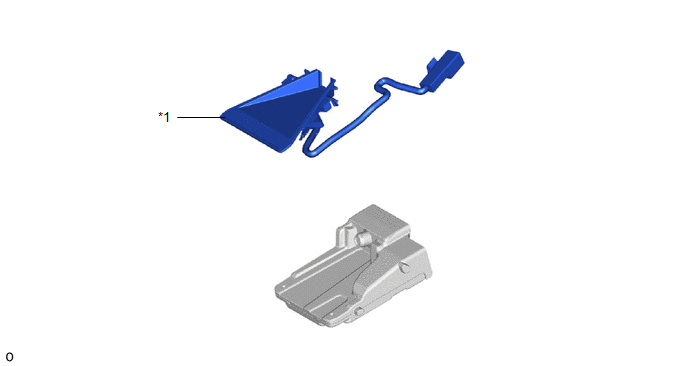
| *1 | FORWARD RECOGNITION WITH HEATER HOOD SUB-ASSEMBLY | - | - |
Removal
REMOVAL
PROCEDURE
1. REMOVE FORWARD RECOGNITION CAMERA
Click here .gif)
2. REMOVE FORWARD RECOGNITION WITH HEATER HOOD SUB-ASSEMBLY
NOTICE:
- Do not touch the inner surface of the forward recognition with heater hood sub-assembly.
- Do not apply force to the heating element of the forward recognition with heater hood sub-assembly or an open circuit may result.
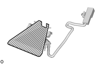
 | Inner Surface of Forward Recognition with Heater Hood Sub-assembly |
| (a) Disconnect the connector. NOTICE: When disconnecting the connector, do not forcibly pull the wire harness. |
|
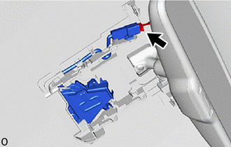
(b) Detach the connector clamp.
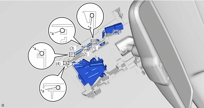
| *a | Wire Harness | - | - |
(c) Remove the wire harness from the guide in the order shown in the illustration.
NOTICE:
Do not pull the harness forcibly when remove the wire harness.
(d) Push the claw and pull the forward recognition with heater hood sub-assembly in the direction indicated by the arrow (1) in the illustration to detach the claw.
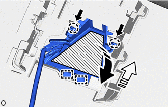
.png) | Push |
 | Remove in this Direction (1) |
 | Remove in this Direction (2) |
| | Heater Area |
NOTICE:
Do not press the heater area.
(e) Pull the forward recognition with heater hood sub-assembly in the direction indicated by the arrow (2) as shown in the illustration to detach the guide and remove the forward recognition with heater hood sub-assembly.
Installation
INSTALLATION
PROCEDURE
1. INSTALL FORWARD RECOGNITION WITH HEATER HOOD SUB-ASSEMBLY
NOTICE:
- Do not touch the inner surface of the forward recognition with heater hood sub-assembly.
- Do not apply force to the heating element of the forward recognition with heater hood sub-assembly or an open circuit may result.

.png) | Inner Surface of Forward Recognition with Heater Hood Sub-assembly |
(a) Insert the forward recognition with heater hood sub-assembly in the direction indicated by the arrow (1) as shown in the illustration to attach the guide.
.png) | Install in this Direction (1) |
.png) | Install in this Direction (2) |
| | Heater Area |
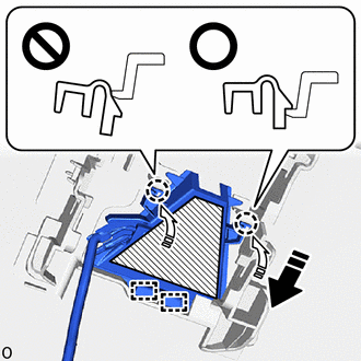
(b) Attach the claw in the direction indicated by the arrow (2) as shown in the illustration.
NOTICE:
- Make sure that the 2 claws are attached as shown in the illustration. Failure to do so may result in the malfunction of systems that use the forward recognition camera.
- Do not apply force to the heating element of the forward recognition with heater hood sub-assembly or an open circuit may result.
HINT:
Check the locking sound of the clip when attaching it.
(c) Install the wire harness to the guide in the order shown in the illustration.

| *a | Wire Harness | - | - |
(d) Attach the connector clamp to install the forward recognition with heater hood sub-assembly.
(e) Connect the connector.
2. INSTALL FORWARD RECOGNITION CAMERA
Click here .gif)
READ NEXT:
 Components
COMPONENTS ILLUSTRATION *1 CRUISE CONTROL MAIN SWITCH - - N*m (kgf*cm, ft.*lbf): Specified torque - -
Removal
REMOVAL PROCEDURE 1. REMOVE HORN BUTTON ASSEMBLY Click here 2. REMOVE CRUISE CONTROL MAIN SWITCH (a) Remove the 2 screws. *a Guide (b) Detach the guide. (c) Disconnect t
SEE MORE:
Radio Receiver Assembly Communication Stop Mode
DESCRIPTION Detection Item Symptom Trouble Area Radio Receiver Assembly Communication Stop Mode Any of the following conditions are met:
Communication stop for "Display and Navigation (AVN)" is indicated on the "Communication Bus Check" screen of the Techstream.
Click here
Comm
Master Module Horizontal Axis Misalignment (C1AC1)
DESCRIPTION This DTC is stored when the angle of the blind spot monitor sensor LH deviates more than the allowable range from the horizontal axis. HINT: If a drum tester such as a speedometer tester, brake/speedometer combination tester or chassis dynamometer is used with the blind spot monitor main
