Lexus NX: Camshaft Position Sensor
Components
COMPONENTS
ILLUSTRATION
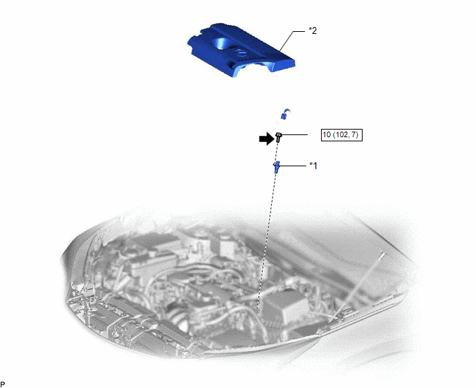
| *1 | CAMSHAFT POSITION SENSOR | *2 | NO. 1 ENGINE COVER SUB-ASSEMBLY |
.png) | N*m (kgf*cm, ft.*lbf) : Specified torque | .png) | Toyota Genuine Adhesive 1324, Three Bond 1324 or equivalent |
| ★ | Precoated part | - | - |
Removal
REMOVAL
PROCEDURE
1. REMOVE NO. 1 ENGINE COVER SUB-ASSEMBLY
Click here .gif)
2. REMOVE CAMSHAFT POSITION SENSOR
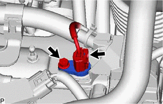
(a) Disconnect the camshaft position sensor connector.
(b) Remove the bolt and camshaft position sensor.
Installation
INSTALLATION
PROCEDURE
1. INSTALL CAMSHAFT POSITION SENSOR
(a) Clean and remove any oil from the threads of the camshaft position sensor installation bolts.
(b) Apply adhesive to 2 or 3 threads of the bolt.
Adhesive:
Toyota Genuine Adhesive 1324, Three Bond 1324 or equivalent.
(c) Apply a light coat of engine oil to the O-ring.
(d) Install the camshaft position sensor with the bolt.
Torque:
10 N·m {102 kgf·cm, 7 ft·lbf}
NOTICE:
- When reusing the camshaft position sensor, check the O-rings.
- Make sure that the O-ring is not cracked or jammed when installing it on the cylinder head cover sub-assembly.
- Replace with a new part if it is dropped or if it receives a strong impact.
(e) Connect the camshaft position sensor connector.
2. INSTALL NO. 1 ENGINE COVER SUB-ASSEMBLY
Click here .gif)
READ NEXT:
 Crankshaft Position Sensor
ComponentsCOMPONENTS ILLUSTRATION *1 CRANKSHAFT POSITION SENSOR - - N*m (kgf*cm, ft.*lbf) : Specified torque Toyota Genuine Adhesive 1324, Three Bond 1324 or equivalent ★
Components
COMPONENTS ILLUSTRATION *A for Compact Spare Tire *B for Full Size Spare Tire *1 DECK FLOOR BOX LH *2 NO. 3 DECK BOARD SUB-ASSEMBLY *3 REAR DECK FLOOR BOX *4 NEGATIVE AUX
SEE MORE:
Inside Vehicle
General MaintenanceGENERAL MAINTENANCE CAUTION / NOTICE / HINT
These are maintenance and inspection items that are considered to be the owner's responsibility.
The owner can do them or they can have them done at a service center. These items include those that should be checked on a daily basis,
Diagnostic Trouble Code Chart
DIAGNOSTIC TROUBLE CODE CHART Power Door Lock Control System DTC No. Detection Item Link B1243 GSW Terminal Circuit Malfunction
