Lexus NX: Components
COMPONENTS
ILLUSTRATION
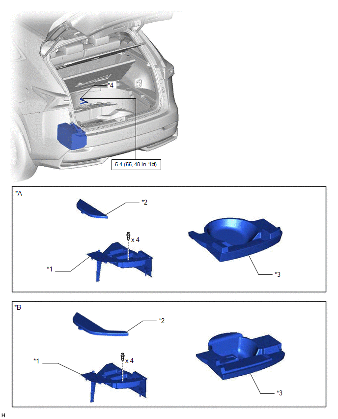
| *A | for Compact Spare Tire | *B | for Full Size Spare Tire |
| *1 | DECK FLOOR BOX LH | *2 | NO. 3 DECK BOARD SUB-ASSEMBLY |
| *3 | REAR DECK FLOOR BOX | *4 | NEGATIVE AUXILIARY BATTERY TERMINAL |
.png) | N*m (kgf*cm, ft.*lbf): Specified torque | - | - |
ILLUSTRATION
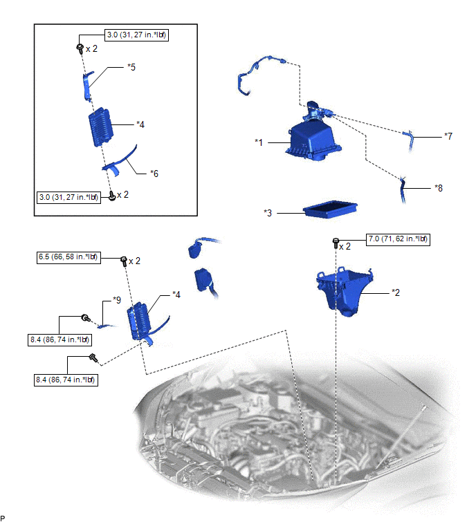
| *1 | AIR CLEANER CAP AND HOSE | *2 | AIR CLEANER CASE SUB-ASSEMBLY |
| *3 | AIR CLEANER FILTER ELEMENT SUB-ASSEMBLY | *4 | ECM |
| *5 | NO. 1 ECM BRACKET | *6 | NO. 2 ECM BRACKET |
| *7 | FUEL VAPOR FEED HOSE | *8 | NO. 2 FUEL VAPOR FEED HOSE |
| *9 | WIRE HARNESS | - | - |
| | N*m (kgf*cm, ft.*lbf): Specified torque | - | - |
READ NEXT:
 Removal
REMOVAL PROCEDURE 1. PRECAUTION NOTICE: After turning the power switch off, waiting time may be required before disconnecting the cable from the negative (-) auxiliary battery terminal. Therefore, mak
Installation
INSTALLATION PROCEDURE 1. INSTALL NO. 2 ECM BRACKET (a) Install the No. 2 ECM bracket to the ECM with the 2 screws. Torque: 3.0 N·m {31 kgf·cm, 27 in·lbf} 2. INSTALL NO. 1 ECM BRACKET (a) Install
SEE MORE:
Terminals Of Ecu
TERMINALS OF ECU CHECK MAIN BODY ECU (MULTIPLEX NETWORK BODY ECU), INSTRUMENT PANEL JUNCTION BLOCK ASSEMBLY *1 Main Body ECU (Multiplex Network Body ECU) - - (a) Remove the main body ECU (multiplex network body ECU) from the instrument panel junction block assembly. Click here (b) Me
Parts Location
PARTS LOCATION ILLUSTRATION *A w/ Parking Assist Monitor System *B w/ Panoramic View Monitor System *1 NO. 2 ENGINE ROOM RELAY BLOCK - DCM FUSE (w/ Manual [SOS] Switch) - ECU-B NO.1 FUSE - ECU-B NO.5 FUSE *2 NO. 1 ENGINE ROOM RELAY BLOCK - AMP FUSE - RADIO FUSE - METER NO.1 FUSE
© 2016-2026 Copyright www.lexunx.com
