Lexus NX: Crankshaft Position Sensor
Components
COMPONENTS
ILLUSTRATION
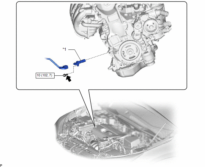
| *1 | CRANKSHAFT POSITION SENSOR | - | - |
.png) | N*m (kgf*cm, ft.*lbf) : Specified torque | .png) | Toyota Genuine Adhesive 1324, Three Bond 1324 or equivalent |
| ★ | Precoated part | - | - |
Removal
REMOVAL
PROCEDURE
1. REMOVE CRANKSHAFT POSITION SENSOR
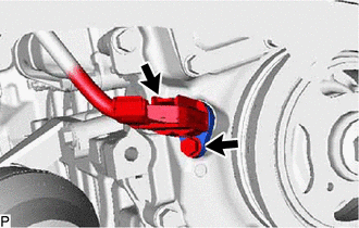
(a) Disconnect the crankshaft position sensor connector.
(b) Remove the bolt and crankshaft position sensor.
Inspection
INSPECTION
PROCEDURE
1. INSPECT CRANKSHAFT POSITION SENSOR
(a) Measure the resistance according to the value(s) in the table below.
Standard Resistance:
| Tester Connection | Condition | Specified Condition |
|---|---|---|
| 1 - 2 | Cold | 1630 to 2740 Ω |
| Hot | 2065 to 3225 Ω |
HINT:
In the table above, the terms "Cold" and "Hot" refer to the temperature of the coils. "Cold" means approximately -10 to 50°C (14 to 122°F). "Hot" means approximately 50 to 100°C (122 to 212°F).
If the result is not as specified, replace the crankshaft position sensor.
Installation
INSTALLATION
PROCEDURE
1. INSTALL CRANKSHAFT POSITION SENSOR
(a) Clean and remove any oil from the threads of the crankshaft position sensor installation bolts.
(b) Apply adhesive to 2 or 3 threads of the bolt.
Adhesive:
Toyota Genuine Adhesive 1324, Three Bond 1324 or equivalent.
(c) Apply a light coat of engine oil to the O-ring.
(d) Install the crankshaft position sensor with the bolt.
Torque:
10 N·m {102 kgf·cm, 7 ft·lbf}
NOTICE:
- When reusing the crankshaft position sensor, check the O-rings.
- Make sure that the O-ring is not cracked or jammed when installing to the timing chain cover assembly.
- Replace with a new part if it is dropped or if it receives a strong impact.
(e) Connect the crankshaft position sensor connector.
READ NEXT:
 Components
COMPONENTS ILLUSTRATION *A for Compact Spare Tire *B for Full Size Spare Tire *1 DECK FLOOR BOX LH *2 NO. 3 DECK BOARD SUB-ASSEMBLY *3 REAR DECK FLOOR BOX *4 NEGATIVE AUX
Removal
REMOVAL PROCEDURE 1. PRECAUTION NOTICE: After turning the power switch off, waiting time may be required before disconnecting the cable from the negative (-) auxiliary battery terminal. Therefore, mak
SEE MORE:
Removal
REMOVAL CAUTION / NOTICE / HINT NOTICE:
Do not replace the spiral with sensor cable sub-assembly with the battery connected and the power switch on (IG).
Do not rotate the spiral with sensor cable sub-assembly when the following conditions are met: 1) The steering wheel is removed, 2) the batte
Start Up Signal Circuit between Radio Receiver Assembly and Navigation ECU
DESCRIPTION This circuit includes the navigation ECU and radio and display receiver assembly. WIRING DIAGRAM PROCEDURE 1. CHECK HARNESS AND CONNECTOR (RADIO RECEIVER ASSEMBLY - NAVIGATION ECU) (a) Disconnect the I153 radio receiver assembly connector. (b) Disconnect the I173 navigation ECU
