Lexus NX: Pcv Valve
Components
COMPONENTS
ILLUSTRATION
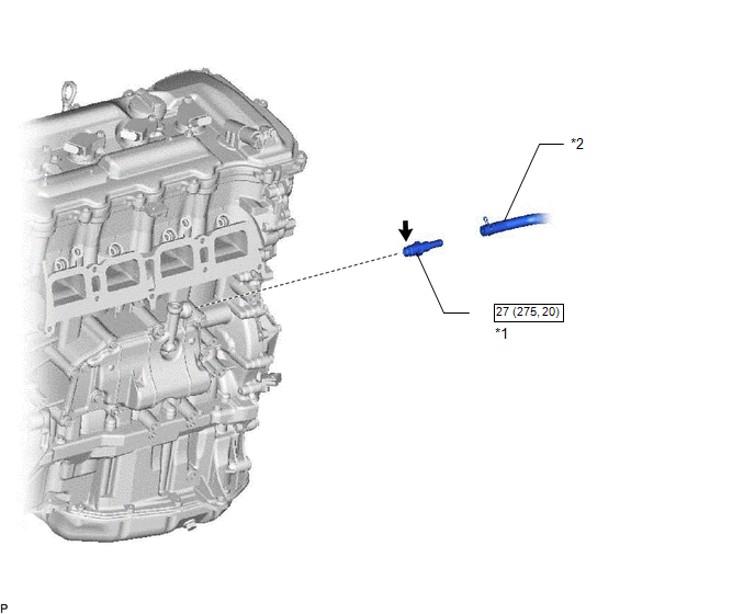
| *1 | PCV VALVE SUB-ASSEMBLY | *2 | NO. 2 PCV HOSE |
.png) | N*m (kgf*cm, ft.*lbf): Specified torque | .png) | Toyota Genuine Adhesive 1324, Three Bond 1324 or equivalent |
| ★ | Precoated part | - | - |
Removal
REMOVAL
PROCEDURE
1. REMOVE INTAKE MANIFOLD
Click here .gif)
2. REMOVE PCV VALVE SUB-ASSEMBLY
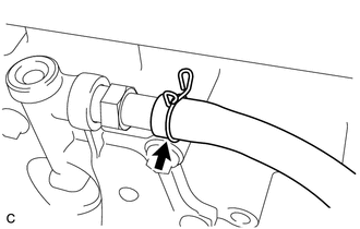
| (a) Slide the clamp and remove the No. 2 PCV hose from the PCV valve sub-assembly. |
|
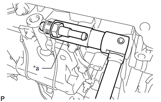
| (b) Using a 19 mm deep socket wrench, remove the PCV valve sub-assembly from the PCV case sub-assembly. |
|
Inspection
INSPECTION
PROCEDURE
1. INSPECT PCV VALVE SUB-ASSEMBLY
(a) Install a clean hose to the PCV valve sub-assembly.
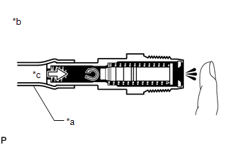
(b) Check the PCV valve operation.
| (1) Blow air into the cylinder block side and check that air passes through easily. CAUTION: Do not suck air through the PCV valve sub-assembly. Petroleum substances inside the PCV valve sub-assembly are hazardous to your health. If the result is not as specified, replace the PCV valve sub-assembly. |
|
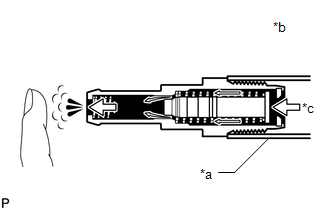
| (2) Blow air into the intake manifold side and check that air passes through with difficulty. If the result is not as specified, replace the PCV valve sub-assembly. CAUTION: Do not suck air through the PCV valve sub-assembly. Petroleum substances inside the PCV valve sub-assembly are hazardous to your health. If the result is not as specified, replace the PCV valve sub-assembly. |
|
Installation
INSTALLATION
PROCEDURE
1. INSTALL PCV VALVE SUB-ASSEMBLY
(a) Apply adhesive to 2 or 3 threads of the PCV valve sub-assembly.
Adhesive:
Toyota Genuine Adhesive 1324, Three Bond 1324 or equivalent
(b) Using a 19 mm deep socket wrench, install the PCV valve sub-assembly to the PCV case sub-assembly.
Torque:
27 N·m {275 kgf·cm, 20 ft·lbf}
(c) Install the No. 2 PCV hose to the PCV valve sub-assembly, and slide the clamp to secure the hose.
2. INSTALL INTAKE MANIFOLD
Click here .gif)
READ NEXT:
 Purge Valve
ComponentsCOMPONENTS ILLUSTRATION *1 PURGE VSV *2 FUEL VAPOR FEED HOSE *3 NO. 2 FUEL VAPOR FEED HOSE - - RemovalREMOVAL PROCEDURE 1. REMOVE PURGE VSV (a) Disconnect the wir
SEE MORE:
On-vehicle Inspection
ON-VEHICLE INSPECTION PROCEDURE 1. INSPECT REAR WIPER MOTOR ASSEMBLY (a) Check the automatic stop (park) position. (1) Operate the rear wiper motor assembly, and then stop the operation. Check the wiper arm automatic stop (park) position. OK: Rear wiper arm stops at the position shown in the ill
Precaution
PRECAUTION PRECAUTION FOR DISCONNECTING CABLE FROM NEGATIVE AUXILIARY BATTERY TERMINAL NOTICE:
After the power switch is turned off, there may be a waiting time before disconnecting the negative (-) auxiliary battery terminal.
Click here
When disconnecting and reconnecting the auxiliary batte
