Lexus NX: Components
COMPONENTS
ILLUSTRATION
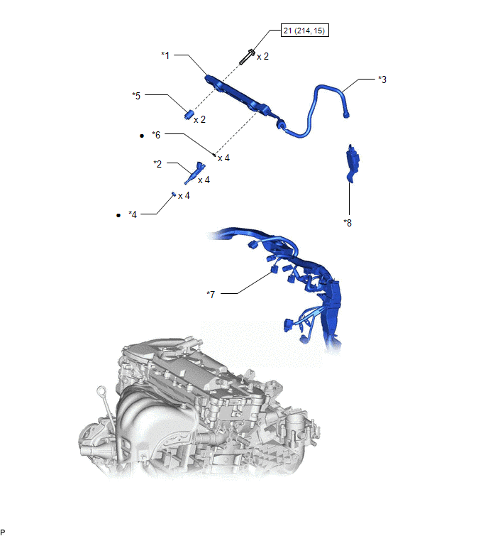
| *1 | FUEL DELIVERY PIPE | *2 | FUEL INJECTOR ASSEMBLY |
| *3 | FUEL TUBE SUB-ASSEMBLY | *4 | INJECTOR VIBRATION INSULATOR |
| *5 | FUEL DELIVERY PIPE SPACER | *6 | O-RING |
| *7 | FUEL INJECTOR ASSEMBLY CONNECTOR | *8 | NO. 1 FUEL PIPE CLAMP |
.png) | N*m (kgf*cm, ft.*lbf): Specified torque | ● | Non-reusable part |
READ NEXT:
 Removal
REMOVAL PROCEDURE 1. DISCONNECT INTAKE MANIFOLD Click here 2. DISCONNECT FUEL TUBE SUB-ASSEMBLY (a) Remove the No. 1 fuel pipe clamp from the fuel tube sub-assembly. Click here (b) Disconnec
Inspection
INSPECTION PROCEDURE 1. INSPECT FUEL INJECTOR ASSEMBLY (a) Measure the resistance according to the value(s) in the table below. Standard Resistance: Tester Connection Condition Specified Condi
Installation
INSTALLATION CAUTION / NOTICE / HINT HINT: Perform "Inspection After Repair" after replacing the fuel injector assembly. Click here PROCEDURE 1. INSTALL FUEL INJECTOR ASSEMBLY HINT: Perform "Inspect
SEE MORE:
Components
COMPONENTS ILLUSTRATION *1 TONNEAU COVER ASSEMBLY - - ILLUSTRATION *1 DECK BOARD ASSEMBLY *2 DECK FLOOR BOX LH *3 NO. 3 DECK BOARD SUB-ASSEMBLY - - ILLUSTRATION *1 NEGATIVE AUXILIARY BATTERY TERMINAL - - N*m (kgf*cm, ft.*lbf): Specified torque -
Data List / Active Test
DATA LIST / ACTIVE TEST DATA LIST NOTICE: In the table below, the values listed under "Normal Condition" are reference values. Do not depend solely on these reference values when deciding whether a part is faulty or not. HINT: Using the Techstream to read the Data List allows the values or states of
© 2016-2026 Copyright www.lexunx.com
