Lexus NX: Removal
REMOVAL
PROCEDURE
1. DISCONNECT INTAKE MANIFOLD
Click here .gif)
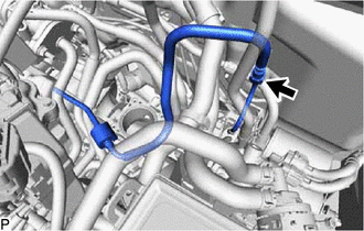
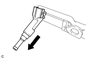
2. DISCONNECT FUEL TUBE SUB-ASSEMBLY
(a) Remove the No. 1 fuel pipe clamp from the fuel tube sub-assembly.
Click here
| (b) Disconnect the fuel tube sub-assembly from the fuel pipe. Click here |
|
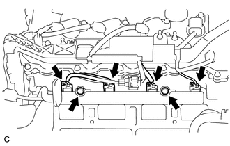
3. REMOVE FUEL DELIVERY PIPE
| (a) Disconnect the 4 fuel injector assembly connectors. |
|
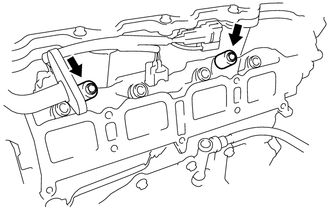
(b) Remove the 2 bolts, and then remove the fuel delivery pipe together with the 4 fuel injector assemblies.
NOTICE:
Be careful not to drop the fuel injector assemblies when removing the fuel delivery pipe.
| (c) Remove the 2 fuel delivery pipe spacers from the cylinder head. |
|
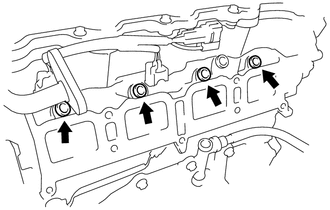
4. REMOVE INJECTOR VIBRATION INSULATOR
| (a) Remove the 4 injector vibration insulators from the cylinder head. |
|
5. REMOVE FUEL INJECTOR ASSEMBLY
| (a) Pull the 4 fuel injector assemblies out of the fuel delivery pipe. |
|
(b) Remove the O-ring from each fuel injector assembly.
NOTICE:
When reinstalling the fuel injector assemblies, mark the cylinder number on the label, etc. and store them in plastic bags to prevent entry of foreign matter.
READ NEXT:
 Inspection
INSPECTION PROCEDURE 1. INSPECT FUEL INJECTOR ASSEMBLY (a) Measure the resistance according to the value(s) in the table below. Standard Resistance: Tester Connection Condition Specified Condi
Installation
INSTALLATION CAUTION / NOTICE / HINT HINT: Perform "Inspection After Repair" after replacing the fuel injector assembly. Click here PROCEDURE 1. INSTALL FUEL INJECTOR ASSEMBLY HINT: Perform "Inspect
Fuel Pressure Regulator
ComponentsCOMPONENTS ILLUSTRATION *1 FUEL PRESSURE REGULATOR ASSEMBLY *2 FUEL PUMP ASSEMBLY WITH FILTER *3 NO. 1 FUEL SUB-TANK *4 NO. 1 FUEL SUCTION SUPPORT *5 FUEL SUCTION
SEE MORE:
Security Horn Circuit
DESCRIPTION When the theft deterrent system is switched from the armed state to the alarm sounding state, the main body ECU (multiplex network body ECU) transmits a signal to cause the security horn to sound at intervals of 0.4 seconds. WIRING DIAGRAM CAUTION / NOTICE / HINT NOTICE:
Inspect the
Cooling Fan Ecu
On-vehicle InspectionON-VEHICLE INSPECTION PROCEDURE 1. INSPECT COOLING FAN ECU (a) Check and ensure the following conditions: (1) The power switch is off. (2) The engine coolant temperature is less than 92°C (198°F). (3) The auxiliary battery voltage is between 11 and 14 V. (4) The A/C switch is
