Lexus NX: Installation
INSTALLATION
CAUTION / NOTICE / HINT
HINT:
Perform "Inspection After Repair" after replacing the fuel injector assembly.
Click here .gif)
PROCEDURE
1. INSTALL FUEL INJECTOR ASSEMBLY
HINT:
Perform "Inspection After Repair" after replacing the fuel injector assembly.
Click here
(a) Apply a light coat of gasoline or spindle oil to a new O-ring, then install it to the fuel injector assembly.
(b) Apply a small amount of gasoline or spindle oil to the fuel injector assembly installation hole of the fuel delivery pipe.
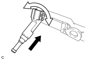
| (c) Insert the fuel delivery pipe while rotating the fuel injector assembly left and right. NOTICE:
|
|
2. INSTALL INJECTOR VIBRATION INSULATOR
(a) Install 4 new injector vibration insulators to the cylinder head.
3. INSTALL FUEL DELIVERY PIPE
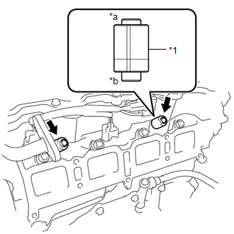
| (a) Install the 2 fuel delivery pipe spacers onto the cylinder head as shown in the illustration. NOTICE: Install the parts in the correct direction. |
|
(b) Install the fuel delivery pipe together with the fuel injector assembly to the cylinder head.
NOTICE:
Do not drop the fuel injector assembly when installing the fuel delivery pipe.
(c) Temporarily install the fuel delivery pipe with the 2 bolts.
(d) Turn the fuel injector assembly by hand and make sure that it is securely installed.
HINT:
If the fuel injector assembly does not rotate smoothly, replace the O-ring with a new one and perform the installation again.
(e) Tighten the 2 bolts to install the fuel delivery pipe.
Torque:
21 N·m {214 kgf·cm, 15 ft·lbf}
(f) Connect the 4 fuel injector assembly connectors.
4. CONNECT FUEL TUBE SUB-ASSEMBLY
(a) Connect the fuel tube sub-assembly to the fuel pipe.
Click here
(b) Install the No. 1 fuel pipe clamp to the fuel tube sub-assembly.
Click here
5. CONNECT INTAKE MANIFOLD
Click here
READ NEXT:
 Fuel Pressure Regulator
ComponentsCOMPONENTS ILLUSTRATION *1 FUEL PRESSURE REGULATOR ASSEMBLY *2 FUEL PUMP ASSEMBLY WITH FILTER *3 NO. 1 FUEL SUB-TANK *4 NO. 1 FUEL SUCTION SUPPORT *5 FUEL SUCTION
Components
COMPONENTS ILLUSTRATION *1 FUEL SUCTION TUBE ASSEMBLY *2 FUEL TANK MAIN TUBE SUB-ASSEMBLY *3 FUEL TANK VENT TUBE SET PLATE *4 TUBE JOINT CLIP *5 FUEL HOSE *6 GASKET
SEE MORE:
Inspection
INSPECTION PROCEDURE 1. INSPECT FUEL LID WITH MOTOR LOCK ASSEMBLY (a) Check the operation of the fuel lid with lock motor assembly. (1) Apply auxiliary battery voltage to the fuel lid with motor lock assembly connector, and check that the fuel lid with motor lock assembly operates smoothly as fol
Adjustment
ADJUSTMENT CAUTION / NOTICE / HINT HINT:
Use the same procedure for the RH and LH sides.
The procedure listed below is for the LH side.
PROCEDURE 1. PREPARE VEHICLE FOR FOG LIGHT AIM ADJUSTMENT (a) Prepare the vehicle:
Ensure that there is no damage or deformation to the vehicle body arou
