Lexus NX: Components
Lexus NX Service Manual / Engine & Hybrid System / 2ar-fxe (intake / Exhaust) / Exhaust Manifold / Components
COMPONENTS
ILLUSTRATION
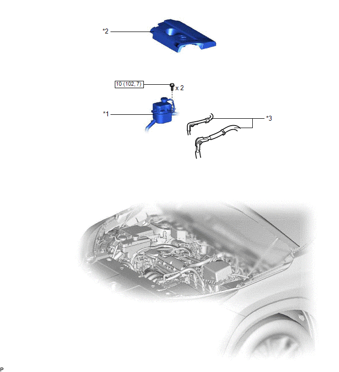
| *1 | INVERTER RESERVOIR ASSEMBLY | *2 | NO. 1 ENGINE COVER SUB-ASSEMBLY |
| *3 | WIRE HARNESS | - | - |
.png) | N*m (kgf*cm, ft.*lbf): Specified torque | - | - |
ILLUSTRATION
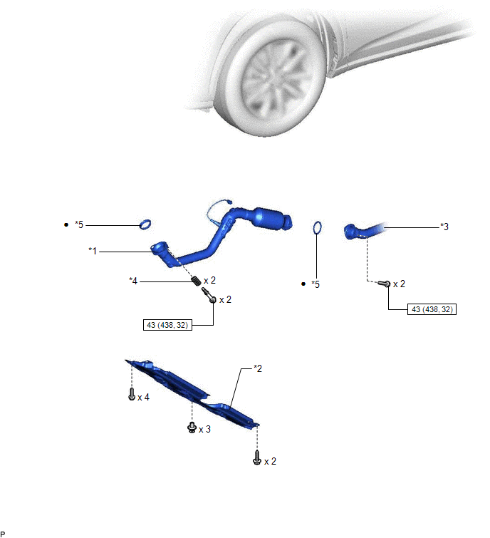
| *1 | FRONT EXHAUST PIPE ASSEMBLY | *2 | NO. 1 ENGINE UNDER COVER ASSEMBLY |
| *3 | CENTER EXHAUST PIPE ASSEMBLY | *4 | COMPRESSION SPRING |
| *5 | GASKET | - | - |
| | N*m (kgf*cm, ft.*lbf): Specified torque | ● | Non-reusable part |
ILLUSTRATION
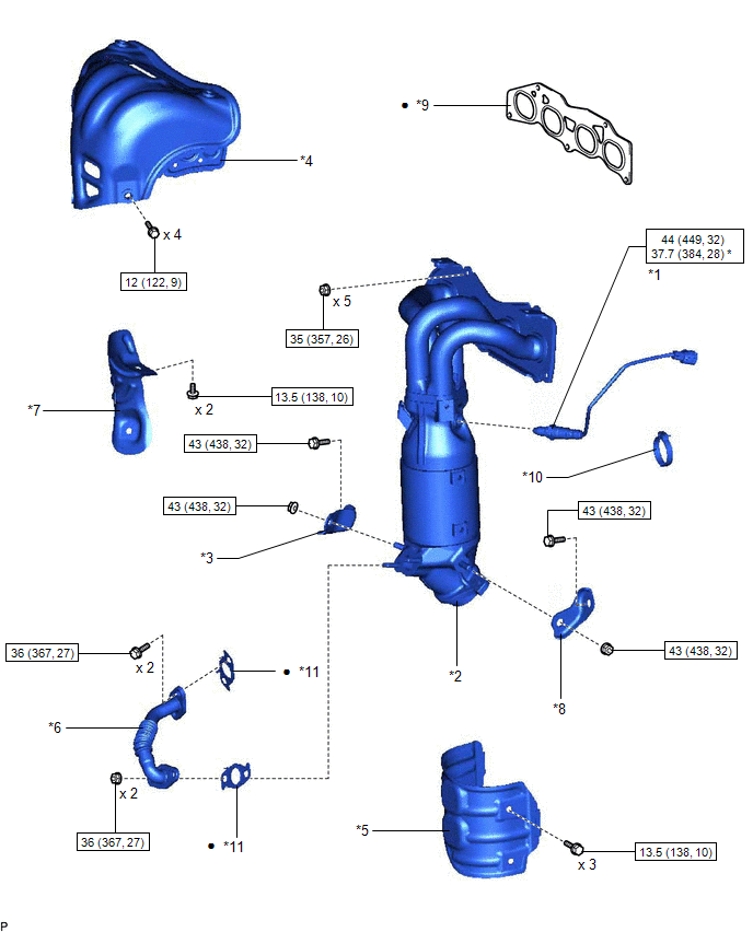
| *1 | AIR FUEL RATIO SENSOR | *2 | EXHAUST MANIFOLD CONVERTER SUB-ASSEMBLY |
| *3 | MANIFOLD STAY | *4 | NO. 1 EXHAUST MANIFOLD HEAT INSULATOR |
| *5 | NO. 1 MANIFOLD CONVERTER INSULATOR | *6 | NO. 2 EGR PIPE |
| *7 | NO. 2 EXHAUST MANIFOLD HEAT INSULATOR | *8 | NO. 2 MANIFOLD STAY |
| *9 | EXHAUST MANIFOLD TO HEAD GASKET | *10 | HOSE CLAMP |
| *11 | GASKET | - | - |
| | N*m (kgf*cm, ft.*lbf): Specified torque | * | For use with SST |
| ● | Non-reusable part | - | - |
READ NEXT:
 Installation
INSTALLATION PROCEDURE 1. INSTALL NO. 2 EXHAUST MANIFOLD HEAT INSULATOR (a) Install the No. 2 exhaust manifold heat insulator with the 2 bolts. Torque: 13.5 N·m {138 kgf·cm, 10 ft·lbf} 2. INSTALL
Components
COMPONENTS ILLUSTRATION *1 CENTER EXHAUST PIPE ASSEMBLY *2 EXHAUST PIPE DAMPER *3 FRONT EXHAUST PIPE ASSEMBLY *4 HEATED OXYGEN SENSOR *5 TAIL EXHAUST PIPE ASSEMBLY *6 EXH
SEE MORE:
Precaution
PRECAUTION CAUTION REGARDING INTERFERENCE WITH ELECTRONIC DEVICES CAUTION:
People with implantable cardiac pacemakers, cardiac resynchronization therapy-pacemakers or implantable cardioverter defibrillators should keep away from the smart access system antennas. The radio waves may affect the ope
How To Proceed With Troubleshooting
CAUTION / NOTICE / HINT HINT: *: Use the Techstream. PROCEDURE 1. VEHICLE BROUGHT TO WORKSHOP
NEXT 2. INSPECT AUXILIARY BATTERY VOLTAGE Standard voltage: 11 to 14 V If the voltage is below 11 V, recharge or replace the auxiliary battery before proceeding.
NE
© 2016-2026 Copyright www.lexunx.com
