
Lexus NX: Components
Lexus NX Service Manual / Vehicle Exterior / Exterior Panels / Trim / Front Door Belt Moulding / Components
COMPONENTS
ILLUSTRATION
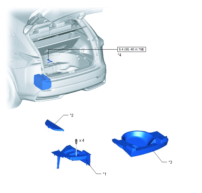
| *1 | DECK FLOOR BOX LH | *2 | NO. 3 DECK BOARD SUB-ASSEMBLY |
| *3 | REAR DECK FLOOR BOX | *4 | NEGATIVE AUXILIARY BATTERY TERMINAL |
.png) | N*m (kgf*cm, ft.*lbf): Specified torque | - | - |
ILLUSTRATION
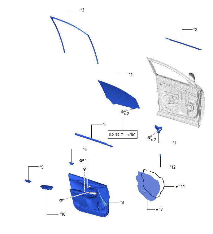
| *1 | FRONT DOOR ARMREST SET BRACKET LH | *2 | FRONT DOOR BELT MOULDING ASSEMBLY LH |
| *3 | FRONT DOOR GLASS RUN LH | *4 | FRONT DOOR GLASS SUB-ASSEMBLY LH |
| *5 | FRONT DOOR INNER GLASS WEATHERSTRIP LH | *6 | FRONT DOOR INSIDE HANDLE BEZEL PLUG LH |
| *7 | FRONT DOOR SERVICE HOLE COVER LH | *8 | FRONT DOOR TRIM BOARD SUB-ASSEMBLY LH |
| *9 | FRONT DOOR TRIM COVER LH | *10 | POWER WINDOW REGULATOR MASTER SWITCH ASSEMBLY WITH FRONT DOOR ARMREST BASE PANEL |
| *11 | BUTYL TAPE | *12 | HOLE PLUG |
| | N*m (kgf*cm, ft.*lbf): Specified torque | ● | Non-reusable part |
READ NEXT:
 Removal
REMOVAL CAUTION / NOTICE / HINT HINT:
Use the same procedure for the RH and LH sides.
The procedure listed below is for the LH side.
PROCEDURE 1. PRECAUTION NOTICE: After the power switch off
Components
COMPONENTS ILLUSTRATION *1 FRONT DOOR LOWER OUTSIDE MOULDING SUB-ASSEMBLY LH *2 HOLE COVER ILLUSTRATION *1 FRONT DOOR UPPER OUTSIDE MOULDING PAD - - ● Non-reusable part
SEE MORE:
Brake Hold Standby Indicator Light Circuit
DESCRIPTION The brake hold standby indicator light turns on if brake hold control is possible when the following conditions required for operation standby are met and the brake hold switch (integration control and panel assembly) is turned on while the power switch is on (IG).
Conditions required
Inspection
INSPECTION CAUTION / NOTICE / HINT NOTICE:
When using a vise, place aluminum plates between the part and vise.
When using a vise, do not overtighten it.
PROCEDURE 1. INSPECT ELECTRIC POWER STEERING COLUMN SUB-ASSEMBLY (a) Secure the electric power steering column sub-assembly in a vise. (
© 2016-2026 Copyright www.lexunx.com
