Lexus NX: Disassembly
DISASSEMBLY
CAUTION / NOTICE / HINT
HINT:
- Use the same procedure for the RH and LH sides.
- The procedure listed below is for the LH side.
PROCEDURE
1. REMOVE OUTER MIRROR LH
Click here .gif)
2. REMOVE SIDE TURN SIGNAL LIGHT ASSEMBLY LH
Click here
3. REMOVE SIDE TELEVISION CAMERA ASSEMBLY LH (w/ Panoramic View Monitor System)
Click here
4. REMOVE OUTER MIRROR RETRACTOR LH
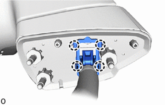
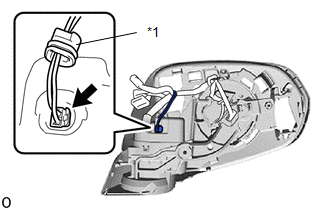
| (a) Detach the 4 claws and remove the hook as shown in the illustration. |
|
| (b) Remove the vinyl tape. |
|
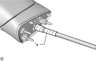
| (c) Cut the harness sub-assembly at the position shown in the illustration. |
|
(d) Detach the 5 guides and remove the gasket as shown in the illustration.
NOTICE:
Make sure to replace the gasket with a new one.
.png) | Remove in this Direction |
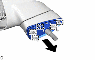
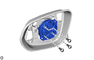
| (e) Using a T25 "TORX" socket wrench, remove the 3 "TORX" screws and base sub-assembly. NOTICE: Make sure to replace the screw with a new one. |
|
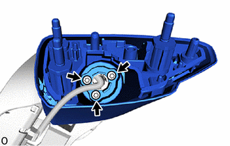
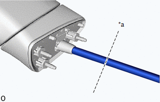
(f) Pass the harness sub-assembly through the base sub-assembly.
| | Remove in this Direction |
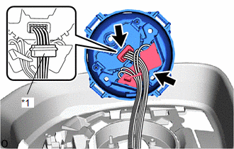
| (g) Remove the connector cover and disconnect the connector. |
|
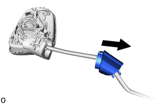
(h) Pull out the harness sub-assembly in the direction indicated by the arrow and detach the harness clamp.
| | Pull Out |
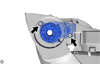
(i) Remove the the actuator sub-assembly.
| (1) Remove the 3 screws and actuator sub-assembly. |
|
| (2) Remove the connector cover and disconnect the 2 connectors. |
|
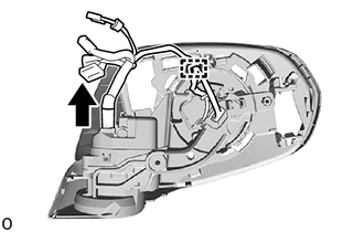
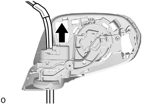
(j) Pull out the harness sub-assembly through the frame sub-assembly as shown in the illustration to remove the harness sub-assembly.
NOTICE:
Make sure to replace the harness sub-assembly with a new one.
| | Pull Out |
| (k) Remove the 2 screws and frame sub-assembly. NOTICE: Make sure to replace the frame sub-assembly with a new one. |
|
READ NEXT:
 Inspection
INSPECTION PROCEDURE 1. INSPECT OUTER REAR VIEW MIRROR ASSEMBLY LH (a) Check the operation of the mirror surface. (1) Disconnect the outer rear view mirror assembly LH connector. *a
Reassembly
REASSEMBLY CAUTION / NOTICE / HINT HINT:
Use the same procedure for the RH and LH sides.
The procedure listed below is for the LH side.
PROCEDURE 1. INSTALL OUTER MIRROR RETRACTOR LH (a) In
Installation
INSTALLATION CAUTION / NOTICE / HINT HINT:
Use the same procedure for the RH and LH sides.
The procedure listed below is for the LH side.
PROCEDURE 1. INSTALL OUTER REAR VIEW MIRROR ASSEMBLY L
SEE MORE:
Head-up display
The head-up display can be used to
project vehicle speed and other
information onto the windshield.
System components
Head-up display
Display brightness will change automatically
according to the brightness of the surrounding
area.
Display position adjustment switch
Display bright
Components
COMPONENTS ILLUSTRATION *1 NAVIGATION ANTENNA ASSEMBLY WITH BRACKET *2 NO. 1 HEATER TO REGISTER DUCT SUB-ASSEMBLY *3 UPPER INSTRUMENT PANEL SUB-ASSEMBLY - - ILLUSTRATION *1 ANTENNA CORD SUB-ASSEMBLY *2 NAVIGATION ANTENNA ASSEMBLY *3 NAVIGATION ANTENNA BRACKET
