Lexus NX: Removal
REMOVAL
CAUTION / NOTICE / HINT
HINT:
- Use the same procedure for the RH and LH sides.
- The procedure listed below is for the LH side.
PROCEDURE
1. REMOVE FRONT DOOR TRIM COVER LH
Click here .gif)
2. REMOVE FRONT DOOR INSIDE HANDLE BEZEL PLUG LH
Click here
3. REMOVE POWER WINDOW REGULATOR MASTER SWITCH ASSEMBLY WITH FRONT DOOR ARMREST BASE PANEL (for Driver Side)
Click here
4. REMOVE POWER WINDOW REGULATOR SWITCH ASSEMBLY WITH FRONT DOOR ARMREST BASE PANEL (for Front Passenger Side)
Click here
5. REMOVE FRONT DOOR TRIM BOARD SUB-ASSEMBLY LH
Click here
6. REMOVE OUTER MIRROR INSTALL HOLE COVER LH
| (a) Detach the clamp. |
|
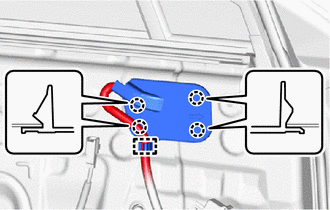
(b) Detach the 4 claws and remove the outer mirror install hole cover LH.
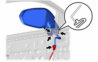
7. REMOVE OUTER REAR VIEW MIRROR ASSEMBLY LH
| (a) w/o Memory: (1) Disconnect the connector. (2) Remove the 3 nuts. (3) Detach the claw and remove the outer rear view mirror assembly LH. |
|
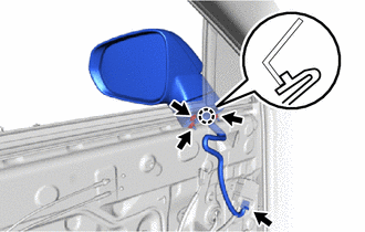
| (b) w/ Memory: (1) Disconnect the connector. (2) Remove the 3 nuts. (3) Detach the claw and remove the outer rear view mirror assembly LH. |
|
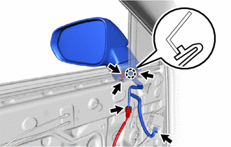
| (c) w/ Panoramic View Monitor System: (1) Disconnect the 2 connectors. (2) Remove the 3 nuts. (3) Detach the claw and remove the outer rear view mirror assembly LH. |
|
READ NEXT:
 Disassembly
DISASSEMBLY CAUTION / NOTICE / HINT HINT:
Use the same procedure for the RH and LH sides.
The procedure listed below is for the LH side.
PROCEDURE 1. REMOVE OUTER MIRROR LH Click here 2. REM
Inspection
INSPECTION PROCEDURE 1. INSPECT OUTER REAR VIEW MIRROR ASSEMBLY LH (a) Check the operation of the mirror surface. (1) Disconnect the outer rear view mirror assembly LH connector. *a
Reassembly
REASSEMBLY CAUTION / NOTICE / HINT HINT:
Use the same procedure for the RH and LH sides.
The procedure listed below is for the LH side.
PROCEDURE 1. INSTALL OUTER MIRROR RETRACTOR LH (a) In
SEE MORE:
Removal
REMOVAL PROCEDURE 1. REMOVE FRONT FLOOR COVER CENTER LH Click here 2. REMOVE CHARCOAL CANISTER ASSEMBLY (a) Disconnect the connector from the canister pump module. *1 Vent Line Hose *2 Air Inlet Line Hose *3 Purge Line Hose *4 Retainer *a Pull Out
Parts Location
PARTS LOCATION ILLUSTRATION *1 POWER STEERING ECU ASSEMBLY - POWER STEERING MOTOR *2 ELECTRIC POWER STEERING COLUMN SUB-ASSEMBLY - TORQUE SENSOR *3 SKID CONTROL ECU (BRAKE BOOSTER WITH MASTER CYLINDER ASSEMBLY) *4 NO. 1 ENGINE ROOM RELAY BLOCK - EPS FUSE *5 COMBINATION METE
