Lexus NX: Components
COMPONENTS
ILLUSTRATION
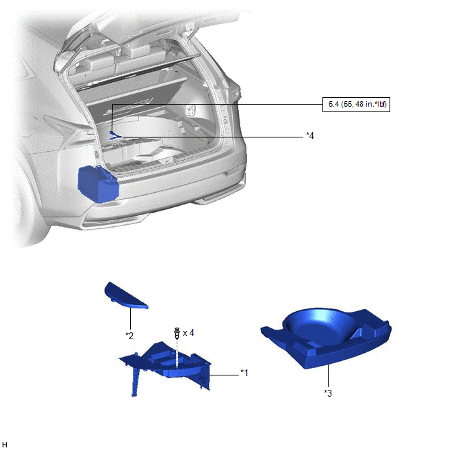
| *1 | DECK FLOOR BOX LH | *2 | NO. 3 DECK BOARD SUB-ASSEMBLY |
| *3 | REAR DECK FLOOR BOX | *4 | NEGATIVE AUXILIARY BATTERY TERMINAL |
.png) | N*m (kgf*cm, ft.*lbf): Specified torque | - | - |
ILLUSTRATION
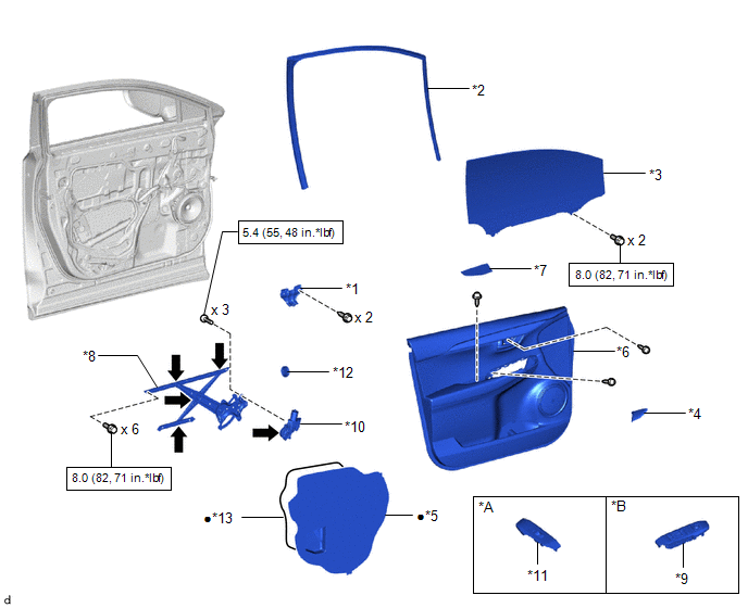
| *A | for Front Passenger Side | *B | for Driver Side |
| *1 | FRONT DOOR ARMREST SET BRACKET LH | *2 | FRONT DOOR GLASS RUN LH |
| *3 | FRONT DOOR GLASS SUB-ASSEMBLY LH | *4 | FRONT DOOR INSIDE HANDLE BEZEL PLUG LH |
| *5 | FRONT DOOR SERVICE HOLE COVER LH | *6 | FRONT DOOR TRIM BOARD SUB-ASSEMBLY LH |
| *7 | FRONT DOOR TRIM COVER LH | *8 | FRONT DOOR WINDOW REGULATOR SUB-ASSEMBLY LH |
| *9 | POWER WINDOW REGULATOR MASTER SWITCH ASSEMBLY WITH FRONT DOOR ARMREST BASE PANEL | *10 | POWER WINDOW REGULATOR MOTOR ASSEMBLY LH |
| *11 | POWER WINDOW REGULATOR SWITCH ASSEMBLY WITH FRONT DOOR ARMREST BASE PANEL | *12 | HOLE PLUG |
| *13 | BUTYL TAPE | - | - |
| | N*m (kgf*cm, ft.*lbf): Specified torque | ● | Non-reusable part |
.png) | MP grease | - | - |
READ NEXT:
 Removal
REMOVAL CAUTION / NOTICE / HINT HINT:
Use the same procedure for the RH and LH sides.
The procedure listed below is for the LH side.
PROCEDURE 1. PRECAUTION NOTICE: After the power switch is t
Inspection
INSPECTION PROCEDURE 1. INSPECT POWER WINDOW REGULATOR MOTOR ASSEMBLY LH NOTICE:
Do not apply voltage to any terminals except terminals 1 and 2 to avoid damaging the pulse sensor inside the motor.
Installation
INSTALLATION CAUTION / NOTICE / HINT HINT:
Use the same procedure for the RH and LH sides.
The procedure listed below is for the LH side.
A bolt without a torque specification is shown in the s
SEE MORE:
Disposal
DISPOSAL CAUTION / NOTICE / HINT CAUTION: Before performing pre-disposal deployment of any SRS part, review and closely follow all applicable environmental and hazardous material regulations. Pre-disposal deployment may be considered hazardous material treatment. PROCEDURE 1. PRECAUTION CAUTION:
Fail-safe Chart
FAIL-SAFE CHART ASC System (a) The stereo component equalizer assembly stores DTCs and freeze frame data and stops sound output if it detects any of the following abnormalities. Item Abnormality Detection Condition Fail-safe Control DTC Output Return Condition CAN communication malfun
