Lexus NX: Removal
REMOVAL
CAUTION / NOTICE / HINT
HINT:
- Use the same procedure for the RH and LH sides.
- The procedure listed below is for the LH side.
PROCEDURE
1. PRECAUTION
NOTICE:
After the power switch is turned off, there may be a waiting time before disconnecting the negative (-) auxiliary battery terminal.
Click here .gif)
2. REMOVE NO. 3 DECK BOARD SUB-ASSEMBLY
Click here
3. REMOVE REAR DECK FLOOR BOX
Click here
4. REMOVE DECK FLOOR BOX LH
Click here
5. DISCONNECT CABLE FROM NEGATIVE AUXILIARY BATTERY TERMINAL
CAUTION:
Wait at least 90 seconds after disconnecting the cable from the auxiliary battery negative (-) terminal to disable the SRS system.
6. REMOVE POWER WINDOW REGULATOR MASTER SWITCH ASSEMBLY WITH FRONT DOOR ARMREST BASE PANEL (for Driver Side)
Click here
7. REMOVE POWER WINDOW REGULATOR SWITCH ASSEMBLY WITH FRONT DOOR ARMREST BASE PANEL (for Front Passenger Side)
Click here
8. REMOVE FRONT DOOR INSIDE HANDLE BEZEL PLUG LH
Click here
9. REMOVE FRONT DOOR TRIM COVER LH
Click here
10. REMOVE FRONT DOOR TRIM BOARD SUB-ASSEMBLY LH
Click here
11. REMOVE FRONT DOOR ARMREST SET BRACKET LH
Click here
12. REMOVE FRONT DOOR SERVICE HOLE COVER LH
Click here
13. REMOVE FRONT DOOR GLASS RUN LH
Click here
14. REMOVE FRONT DOOR GLASS SUB-ASSEMBLY LH
Click here
15. REMOVE FRONT DOOR WINDOW REGULATOR SUB-ASSEMBLY LH
Click here
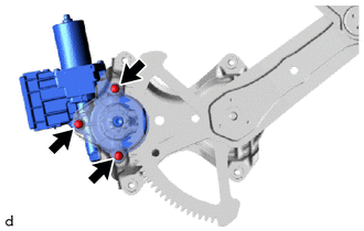
16. REMOVE POWER WINDOW REGULATOR MOTOR ASSEMBLY LH
| (a) Using a T25 "TORX" socket wrench, remove the 3 "TORX" screws and power window regulator motor assembly LH. |
|
READ NEXT:
 Inspection
INSPECTION PROCEDURE 1. INSPECT POWER WINDOW REGULATOR MOTOR ASSEMBLY LH NOTICE:
Do not apply voltage to any terminals except terminals 1 and 2 to avoid damaging the pulse sensor inside the motor.
Installation
INSTALLATION CAUTION / NOTICE / HINT HINT:
Use the same procedure for the RH and LH sides.
The procedure listed below is for the LH side.
A bolt without a torque specification is shown in the s
SEE MORE:
Lost Communication with Rear Gate Module (U0230)
DESCRIPTION DTC No. Detection Item DTC Detection Condition Trouble Area DTC Output from U0230 Lost Communication with Rear Gate Module There is no communication from the multiplex network door ECU.
Power source circuit of multiplex network door ECU
Multiplex network door EC
Parts Location
PARTS LOCATION ILLUSTRATION *1 INNER REAR VIEW MIRROR ASSEMBLY *2 OUTER REAR VIEW MIRROR ASSEMBLY LH *3 OUTER REAR VIEW MIRROR ASSEMBLY RH *4 OUTER MIRROR LH *5 OUTER MIRROR RH *6 OUTER MIRROR CONTROL ECU ASSEMBLY LH *7 OUTER MIRROR CONTROL ECU ASSEMBLY RH *8
