Lexus NX: Components
COMPONENTS
ILLUSTRATION
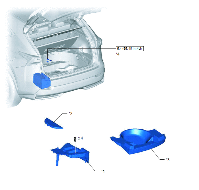
| *1 | DECK FLOOR BOX LH | *2 | NO. 3 DECK BOARD SUB-ASSEMBLY |
| *3 | REAR DECK FLOOR BOX | *4 | NEGATIVE AUXILIARY BATTERY TERMINAL |
.png) | N*m (kgf*cm, ft.*lbf): Specified torque | - | - |
ILLUSTRATION
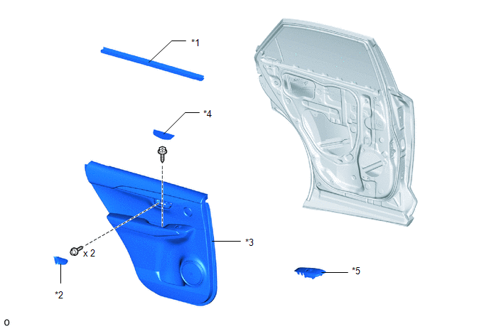
| *1 | REAR DOOR INNER GLASS WEATHERSTRIP LH | *2 | REAR DOOR INSIDE HANDLE BEZEL PLUG LH |
| *3 | REAR DOOR TRIM BOARD SUB-ASSEMBLY LH | *4 | REAR DOOR TRIM COVER LH |
| *5 | REAR POWER WINDOW REGULATOR SWITCH ASSEMBLY WITH REAR DOOR ARMREST BASE PANEL | - | - |
ILLUSTRATION
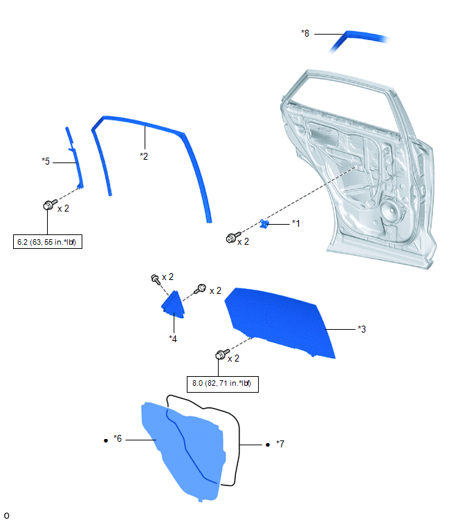
| *1 | REAR DOOR ARMREST SET BRACKET LH | *2 | REAR DOOR GLASS RUN LH |
| *3 | REAR DOOR GLASS SUB-ASSEMBLY LH | *4 | REAR DOOR REAR GUIDE SEAL LH |
| *5 | REAR DOOR REAR LOWER WINDOW FRAME SUB-ASSEMBLY LH | *6 | REAR DOOR SERVICE HOLE COVER LH |
| *7 | BUTYL TAPE | *8 | REAR DOOR WEATHERSTRIP LH |
| | N*m (kgf*cm, ft.*lbf): Specified torque | ● | Non-reusable part |
ILLUSTRATION
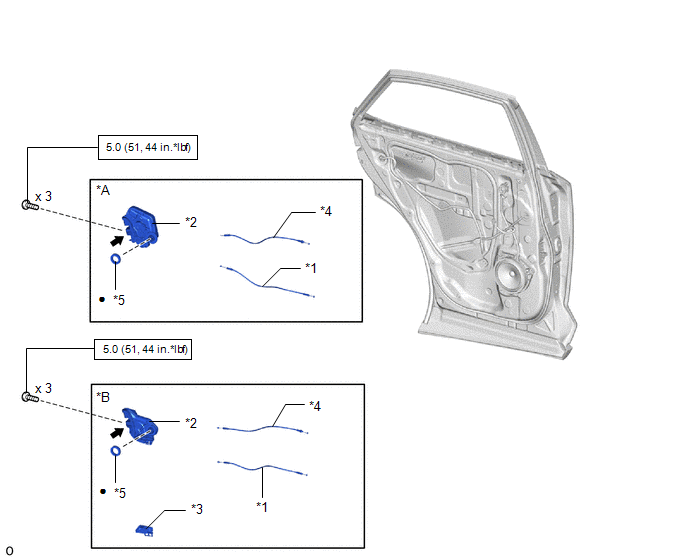
| *A | w/ Double Locking System | *B | w/o Double Locking System |
| *1 | REAR DOOR INSIDE LOCKING CABLE ASSEMBLY LH | *2 | REAR DOOR LOCK ASSEMBLY LH |
| *3 | REAR DOOR LOCK COVER SUB-ASSEMBLY LH | *4 | REAR DOOR LOCK REMOTE CONTROL CABLE ASSEMBLY LH |
| *5 | DOOR LOCK WIRING HARNESS SEAL | - | - |
| | N*m (kgf*cm, ft.*lbf): Specified torque | ● | Non-reusable part |
.png) | MP grease | - | - |
READ NEXT:
 Removal
REMOVAL CAUTION / NOTICE / HINT HINT:
Use the same procedure for the RH and LH sides.
The procedure listed below is for the LH side.
PROCEDURE 1. PRECAUTION NOTICE: After turning the power swi
Inspection
INSPECTION PROCEDURE 1. INSPECT REAR DOOR LOCK ASSEMBLY LH (a) Check the door lock motor operation. (1) Apply auxiliary battery voltage to the motor connector and check the operation of the door lo
Installation
INSTALLATION CAUTION / NOTICE / HINT HINT:
Use the same procedure for the RH and LH sides.
The procedure listed below is for the LH side.
A bolt without a torque specification is shown in the s
SEE MORE:
Headlight Cleaner Motor
ComponentsCOMPONENTS ILLUSTRATION *1 FRONT BUMPER ASSEMBLY *2 HEADLIGHT CLEANER MOTOR AND PUMP ASSEMBLY RemovalREMOVAL PROCEDURE 1. REMOVE FRONT BUMPER ASSEMBLY Click here 2. REMOVE HEADLIGHT CLEANER MOTOR AND PUMP ASSEMBLY (a) Loosen the clip and remove the headlight cleaner ho
Motor Rotation Angle Sensor (C1528)
DESCRIPTION The motor rotation angle sensor detects the motor rotation angle and sends this information to the power steering ECU assembly. DTC No. Detection Item DTC Detection Condition Trouble Area Warning Indicate Return-to-normal Condition C1528 Motor Rotation Angle Sensor M
