
Lexus NX: Headlight Cleaner Motor
Components
COMPONENTS
ILLUSTRATION
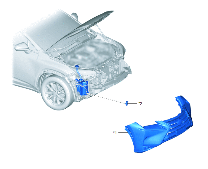
| *1 | FRONT BUMPER ASSEMBLY | *2 | HEADLIGHT CLEANER MOTOR AND PUMP ASSEMBLY |
Removal
REMOVAL
PROCEDURE
1. REMOVE FRONT BUMPER ASSEMBLY
Click here .gif)
2. REMOVE HEADLIGHT CLEANER MOTOR AND PUMP ASSEMBLY
| (a) Loosen the clip and remove the headlight cleaner hose. |
|
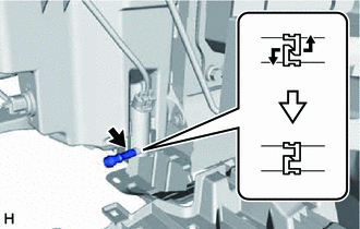
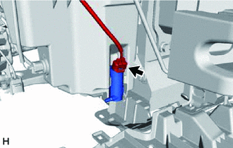
| (b) Disconnect the connector. |
|
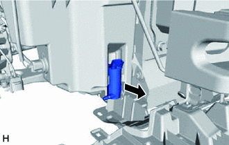
| (c) Remove the headlight cleaner motor and pump assembly. |
|
Inspection
INSPECTION
PROCEDURE
1. INSPECT HEADLIGHT CLEANER MOTOR AND PUMP ASSEMBLY
HINT:
This check should be performed with the headlight cleaner motor and pump assembly installed on the washer jar.
(a) Fill the washer jar with washer fluid.
| (b) Connect an auxiliary battery positive (+) lead to terminal 2 of the headlight cleaner motor and pump assembly, and an auxiliary battery negative (-) lead to terminal 1. |
|
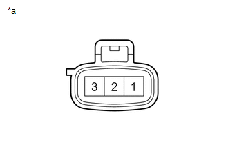
(c) Check that washer fluid flows from the washer jar.
OK:
Washer fluid flows from the washer jar.
If the result is not as specified, replace the headlight cleaner motor and pump assembly.
Installation
INSTALLATION
PROCEDURE
1. INSTALL HEADLIGHT CLEANER MOTOR AND PUMP ASSEMBLY
(a) Install the headlight cleaner motor and pump assembly.
(b) Connect the connector.
| (c) Install the headlight cleaner hose with the clip. |
|
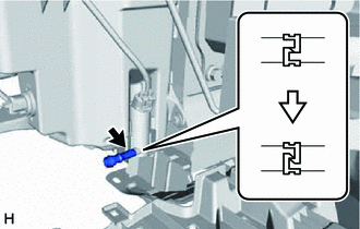
2. INSTALL FRONT BUMPER ASSEMBLY
Click here .gif)
READ NEXT:
 Components
COMPONENTS ILLUSTRATION *1 RAIN SENSOR *2 RAIN SENSOR COVER *3 RAIN SENSOR TAPE - -
On-vehicle Inspection
ON-VEHICLE INSPECTION PROCEDURE 1. INSPECT RAIN SENSOR (a) Remove the rain sensor cover. Click here (b) Disconnect the rain sensor connector. *a Front view of wire harness connecto
SEE MORE:
Components
COMPONENTS ILLUSTRATION *1 DECK FLOOR BOX LH *2 NO. 3 DECK BOARD SUB-ASSEMBLY *3 REAR DECK FLOOR BOX *4 NEGATIVE AUXILIARY BATTERY TERMINAL N*m (kgf*cm, ft.*lbf): Specified torque - - ILLUSTRATION *1 ECU INTEGRATION BOX RH *2 GLOVE COMPARTMENT DOOR ASSEMBL
Removal
REMOVAL CAUTION / NOTICE / HINT NOTICE:
When replacing the forward recognition camera, replace it with a new one.
Replace the forward recognition camera if there is any foreign matter on the camera lens.
Do not touch the camera lens or the front windshield glass in front of the camera.
If t
