Lexus NX: Motor Rotation Angle Sensor (C1528)
DESCRIPTION
The motor rotation angle sensor detects the motor rotation angle and sends this information to the power steering ECU assembly.
| DTC No. | Detection Item | DTC Detection Condition | Trouble Area | Warning Indicate | Return-to-normal Condition |
|---|---|---|---|---|---|
| C1528 | Motor Rotation Angle Sensor | Motor rotation angle sensor malfunction |
| On | Power switch on (IG) again |
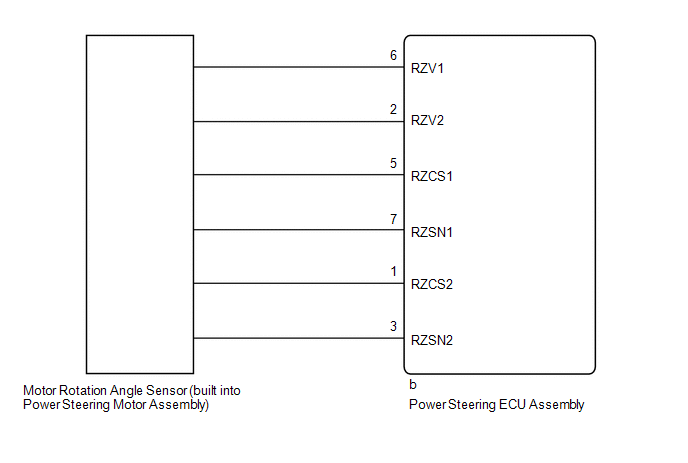
WIRING DIAGRAM
CAUTION / NOTICE / HINT
NOTICE:
If the power steering ECU assembly has been replaced, perform assist map writing.
Click here .gif)
PROCEDURE
| 1. | CHECK CONNECTOR CONNECTION CONDITION |
(a) Check the connection condition of the motor rotation angle sensor connector.
OK:
Motor rotation angle sensor connector is securely connected to the power steering ECU assembly.
| NG | .gif) | CONNECT CONNECTOR |
|
.gif)
| 2. | READ VALUE USING TECHSTREAM (MOTOR ROTATION ANGLE) |
(a) Turn the power switch off.
(b) Connect the Techstream to the DLC3.
(c) Turn the power switch on (READY).
(d) Turn the Techstream on.
(e) Enter the following menus: Chassis / EMPS / Data List.
(f) Select the item "Motor Rotation Angle" in the Data List and read the value displayed on the Techstream.
Chassis > EMPS > Data List| Tester Display | Measurement Item | Range | Normal Condition | Diagnostic Note |
|---|---|---|---|---|
| Motor Rotation Angle | Motor rotation angle | Min.: 0.000 deg Max.: 1441.770 deg | Power switch on (READY) and steering wheel being turned: During steering operation, motor rotation angle value changes from 0 to 360 deg | - |
| Tester Display |
|---|
| Motor Rotation Angle |
OK:
During steering operation, motor rotation angle value changes from 0 to 360°.
| OK | | REPLACE POWER STEERING ECU ASSEMBLY |
|
| 3. | CHECK POWER STEERING MOTOR ASSEMBLY (MOTOR ROTATION ANGLE SENSOR) |
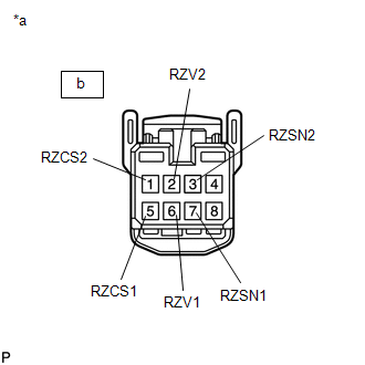
| (a) Disconnect the b motor rotation angle sensor connector. |
|
(b) Measure the resistance according to the value(s) in the table below.
Standard Resistance:
| Tester Connection | Condition | Specified Condition |
|---|---|---|
| b-6 (RZV1) - b-2 (RZV2) | 25°C (77°F) | 14.0 to 17.2 Ω |
| b-5 (RZCS1) - b-1 (RZCS2) | 25°C (77°F) | 25.8 to 31.6 Ω |
| b-7 (RZSN1) - b-3 (RZSN2) | 25°C (77°F) | 25.8 to 31.6 Ω |
| OK | | REPLACE POWER STEERING ECU ASSEMBLY |
| NG | | REPLACE POWER STEERING MOTOR ASSEMBLY |
READ NEXT:
 Vehicle Speed Signal (C1541)
DESCRIPTION The power steering ECU assembly receives vehicle speed signals from the skid control ECU via CAN communication. The ECU provides appropriate assisting force in accordance with the vehicle
IG Power Supply Voltage (C1551)
DESCRIPTION The power steering ECU assembly distinguishes the power switch status as on (IG) or off through the IG power source circuit. DTC No. Detection Item DTC Detection Condition Trouble
PIG Power Supply Voltage (C1552,C1554)
DESCRIPTION When a problem occurs in the power steering system, the power source relay circuit is shut off to stop the power assist. DTC No. Detection Item DTC Detection Condition Trouble Are
SEE MORE:
Removal
REMOVAL PROCEDURE 1. REMOVE INSTRUMENT SIDE PANEL LH Click here 2. REMOVE NO. 1 INSTRUMENT PANEL SAFETY PAD SUB-ASSEMBLY Click here 3. REMOVE TRIP SWITCH (LIGHT CONTROL RHEOSTAT) (a) Using a screwdriver, detach the 2 claws and remove the trip switch (light control rheostat). HINT: Tape th
Speaker Output Short (B15C3)
DESCRIPTION This DTC is stored when a malfunction occurs in the speakers. In addition, the radio receiver assembly detects a malfunction via the stereo component amplifier assembly. DTC No. Detection Item DTC Detection Condition Trouble Area B15C3 Speaker Output Short A short is det
