Lexus NX: Components
Lexus NX Service Manual / Vehicle Interior / Heating / Air Conditioning / Ptc Heater Assembly / Components
COMPONENTS
ILLUSTRATION
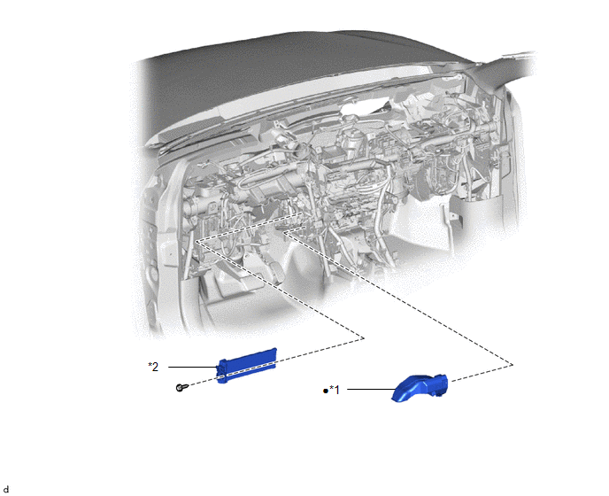
| *1 | NO. 1 AIR DUCT | *2 | QUICK HEATER ASSEMBLY |
| ● | Non-reusable part | - | - |
READ NEXT:
 Removal
REMOVAL PROCEDURE 1. REMOVE LOWER INSTRUMENT PANEL Click here 2. REMOVE NO. 1 AIR DUCT Click here 3. REMOVE QUICK HEATER ASSEMBLY (a) Detach the clamp and disconnect the 2 connectors.
Inspection
INSPECTION PROCEDURE 1. INSPECT QUICK HEATER ASSEMBLY (a) Measure the resistance according to the value(s) in the table below. Standard Resistance: Tester Connection Condition Specified Con
Installation
INSTALLATION PROCEDURE 1. INSTALL QUICK HEATER ASSEMBLY (a) Install the quick heater assembly with the screw. (b) Attach the clamp and connect the 2 connectors. 2. INSTALL NO. 1 AIR DUC
SEE MORE:
Vehicle Control History
VEHICLE CONTROL HISTORY NOTICE: When checking the vehicle control history, make sure to record the output histories. Then, remove the histories and recheck the output histories again. CHECK VEHICLE CONTROL HISTORY (PRE-COLLISION SYSTEM) (a) Connect the Techstream to the DLC3. (b) Turn the power swit
Parts Location
PARTS LOCATION ILLUSTRATION *1 COOLING FAN RELAY (FAN NO. 1) *2 COOLING FAN ECU *3 COOLING FAN MOTOR *4 CRANKSHAFT POSITION SENSOR *5 ECM *6 NO. 2 ENGINE ROOM RELAY BLOCK - FAN FUSE *7 NO. 2 COOLING FAN MOTOR *8 INSTRUMENT PANEL JUNCTION BLOCK - ECU-IG NO. 4 F
© 2016-2026 Copyright www.lexunx.com
