Lexus NX: Components
COMPONENTS
ILLUSTRATION
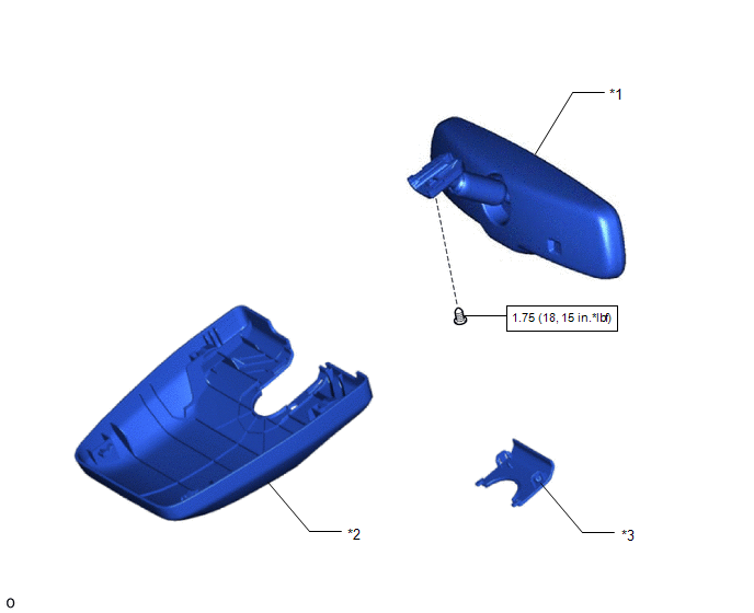
| *1 | INNER REAR VIEW MIRROR ASSEMBLY | *2 | NO. 1 FORWARD RECOGNITION COVER |
| *3 | NO. 2 FORWARD RECOGNITION COVER | - | - |
.png) | N*m (kgf*cm, ft.*lbf): Specified torque | - | - |
READ NEXT:
 System Diagram
SYSTEM DIAGRAM
Calibration
CALIBRATION SELECT COMPASS DISPLAY MODE (w/ Compass) (a) The compass switch allows selection of the compass display. *1 Compass Display *2 Compass Switch PERFORM CALIBRATION (w/ Compass
Problem Symptoms Table
PROBLEM SYMPTOMS TABLE HINT: Use the table below to help determine the cause of problem symptoms. If multiple suspected areas are listed, the potential causes of the symptoms are listed in order of pr
SEE MORE:
Front Fog Light Circuit
DESCRIPTION Illumination of the front fog lights is controlled by the main body ECU (multiplex network body ECU). WIRING DIAGRAM CAUTION / NOTICE / HINT NOTICE:
Inspect the fuses for circuits related to this system before performing the following inspection procedure.
Before performing trouble
Airbag ECU Malfunction (B1000)
DESCRIPTION The airbag ECU assembly consists of a deceleration sensor, safing sensor, drive circuit, diagnosis circuit, ignition control, etc. If the airbag ECU assembly receives signals from the deceleration sensor, it determines whether or not the SRS should be activated. DTC B1000 is stored when
© 2016-2026 Copyright www.lexunx.com
