Lexus NX: Components
COMPONENTS
ILLUSTRATION
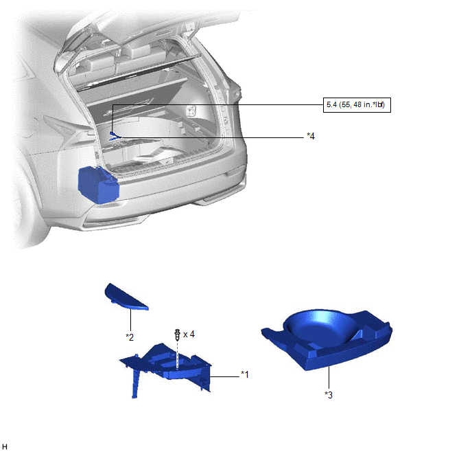
| *1 | DECK FLOOR BOX LH | *2 | NO. 3 DECK BOARD SUB-ASSEMBLY |
| *3 | REAR DECK FLOOR BOX | *4 | NEGATIVE AUXILIARY BATTERY TERMINAL |
.png) | N*m (kgf*cm, ft.*lbf): Specified torque | - | - |
ILLUSTRATION
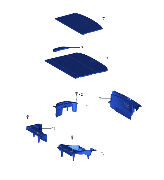
| *1 | DECK BOARD ASSEMBLY | *2 | DECK FLOOR BOX RH |
| *3 | NO. 1 TOOL BOX SUB-ASSEMBLY | *4 | NO. 2 DECK BOARD SUB-ASSEMBLY |
| *5 | NO. 2 TOOL BOX SUB-ASSEMBLY | *6 | REAR FLOOR FINISH PLATE |
| *7 | TONNEAU COVER ASSEMBLY | - | - |
ILLUSTRATION
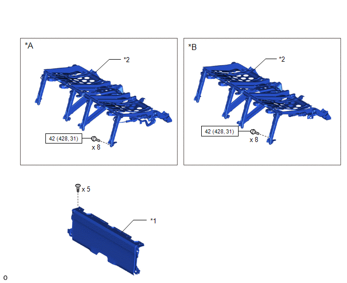
| *A | for Manual Seat | *B | for Power Seat |
| *1 | BATTERY SERVICE COVER BOARD | *2 | NO. 1 SEAT LEG ASSEMBLY |
| | N*m (kgf*cm, ft.*lbf): Specified torque | - | - |
ILLUSTRATION
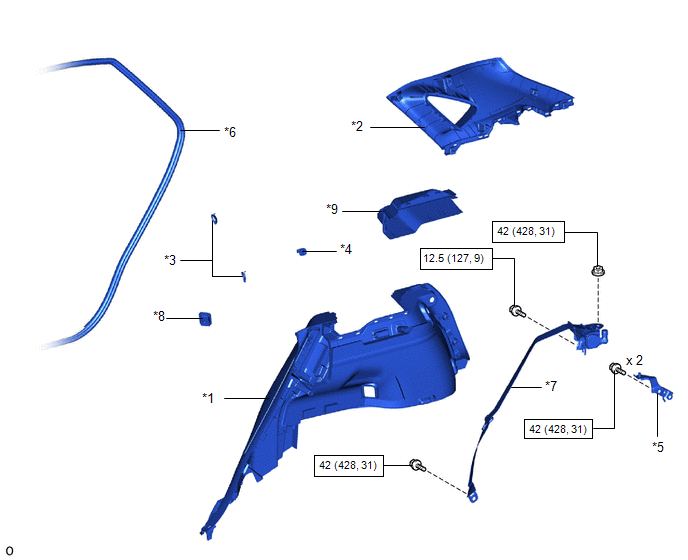
| *1 | DECK TRIM SIDE PANEL ASSEMBLY LH | *2 | INNER ROOF SIDE GARNISH ASSEMBLY LH |
| *3 | LUGGAGE HOLD BELT STRIKER ASSEMBLY | *4 | NO. 1 LUGGAGE COMPARTMENT TRIM HOOK |
| *5 | OUTER BELT ANCHOR BRACKET SUB-ASSEMBLY LH | *6 | REAR DOOR OPENING TRIM WEATHERSTRIP LH |
| *7 | REAR NO. 1 SEAT OUTER BELT ASSEMBLY LH | *8 | ROPE HOOK ASSEMBLY |
| *9 | UPPER DECK TRIM SIDE BOARD LH | - | - |
| | N*m (kgf*cm, ft.*lbf): Specified torque | - | - |
READ NEXT:
 Removal
REMOVAL CAUTION / NOTICE / HINT HINT:
Use the same procedure for the RH and LH sides.
The procedure listed below is for the LH side.
PROCEDURE 1. PRECAUTION NOTICE: After the power switch is t
Inspection
INSPECTION PROCEDURE 1. INSPECT REAR NO. 1 SEAT OUTER BELT ASSEMBLY (a) Before installing the rear No. 1 seat outer belt assembly, check the ELR function. NOTICE: Do not disassemble the retractor.
Installation
INSTALLATION CAUTION / NOTICE / HINT HINT:
Use the same procedure for the RH and LH sides.
The procedure listed below is for the LH side.
A bolt without a torque specification is shown in the s
SEE MORE:
Steering Angle Initialization Incomplete (C1694)
DESCRIPTION This DTC is stored when the rear television camera assembly judges that the maximum steering angle has not been memorized (steering angle setting is incomplete). DTC No. Detection Item DTC Detection Condition Trouble Area C1694 Steering Angle Initialization Incomplete Ma
Steering Angle Sensor
ComponentsCOMPONENTS ILLUSTRATION *A w/o Steering Heater *B w/ Steering Heater *1 STEERING SENSOR *2 SPIRAL CABLE SUB-ASSEMBLY RemovalREMOVAL PROCEDURE 1. REMOVE SPIRAL W/SENSOR CABLE SUB-ASSEMBLY Click here 2. REMOVE STEERING SENSOR (a) Disengage the 6 claws and 2 pi
