Lexus NX: Installation
INSTALLATION
CAUTION / NOTICE / HINT
HINT:
- Use the same procedure for the RH and LH sides.
- The procedure listed below is for the LH side.
-
A bolt without a torque specification is shown in the standard bolt chart.
Click here
.gif)
PROCEDURE
1. INSTALL OUTER BELT ANCHOR BRACKET SUB-ASSEMBLY LH
(a) Attach the guide and install the outer belt anchor bracket sub-assembly LH with the 2 bolts.
Torque:
42 N·m {428 kgf·cm, 31 ft·lbf}
2. INSTALL REAR NO. 1 SEAT OUTER BELT ASSEMBLY LH
| (a) Attach the 2 guides and temporarily install the rear No. 1 seat outer belt assembly LH with the bolt and nut. |
|
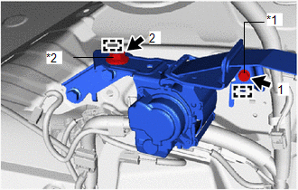
(b) Tighten the bolt and nut in the order shown in the illustration.
Torque:
Bolt :
12.5 N·m {127 kgf·cm, 9 ft·lbf}
Nut :
42 N·m {428 kgf·cm, 31 ft·lbf}
3. INSTALL INNER ROOF SIDE GARNISH ASSEMBLY LH
Click here
4. INSTALL DECK TRIM SIDE PANEL ASSEMBLY LH
Click here
5. INSTALL UPPER DECK TRIM SIDE BOARD LH
Click here
6. INSTALL NO. 1 LUGGAGE COMPARTMENT TRIM HOOK
Click here
7. INSTALL LUGGAGE HOLD BELT STRIKER ASSEMBLY
Click here
8. INSTALL ROPE HOOK ASSEMBLY
Click here
9. INSTALL REAR DOOR OPENING TRIM WEATHERSTRIP LH
Click here
10. INSTALL NO. 1 SEAT LEG ASSEMBLY
-
for Manual Seat:
Click here
-
for Power Seat:
Click here
11. INSTALL BATTERY SERVICE COVER BOARD
-
for Manual Seat:
Click here
-
for Power Seat:
Click here
12. INSTALL REAR FLOOR FINISH PLATE
Click here
13. INSTALL NO. 2 TOOL BOX SUB-ASSEMBLY
Click here
14. INSTALL NO. 1 TOOL BOX SUB-ASSEMBLY
Click here
15. INSTALL DECK FLOOR BOX RH
Click here
16. INSTALL DECK FLOOR BOX LH
Click here
17. INSTALL NO. 2 DECK BOARD SUB-ASSEMBLY
Click here
18. INSTALL TONNEAU COVER ASSEMBLY
Click here
19. INSTALL REAR SEAT ASSEMBLY
-
for Manual Seat:
Click here
-
for Power Seat:
Click here
20. CONNECT CABLE TO NEGATIVE AUXILIARY BATTERY TERMINAL
21. INITIALIZATION AFTER RECONNECTING AUXILIARY BATTERY TERMINAL
Click here
HINT:
When disconnecting and reconnecting the auxiliary battery, there is an automatic learning function that completes learning when the respective system is used.
Click here
22. INSTALL DECK FLOOR BOX LH
Click here
23. INSTALL REAR DECK FLOOR BOX
Click here
24. INSTALL NO. 3 DECK BOARD SUB-ASSEMBLY
Click here
25. INSTALL DECK BOARD ASSEMBLY
Click here
26. INSPECT SRS WARNING LIGHT
Click here
READ NEXT:
 Seat Belt Tension Reducer System
Parts LocationPARTS LOCATION ILLUSTRATION *A w/ Memory - - *1 FRONT SEAT INNER BELT ASSEMBLY RH *2 FRONT SEAT INNER BELT ASSEMBLY LH *3 FRONT SEAT OUTER BELT ASSEMBLY RH *
Components
COMPONENTS ILLUSTRATION *1 AIR CONDITIONING CONTROL ASSEMBLY (SEAT BELT WARNING LIGHT) *2 CENTER INSTRUMENT CLUSTER FINISH PANEL ASSEMBLY *3 COWL SIDE TRIM BOARD LH *4 DOOR SCUFF P
SEE MORE:
Slide Sensor Malfunction (B2650)
DESCRIPTION When the front power seat switch LH does not receive a sensor signal despite forward or backward movement of the seat by power seat motor operation, this DTC is stored. DTC No. Detection Item DTC Detection Condition Trouble Area B2650 Slide Sensor Malfunction The forward
Interior Light Auto Cut Circuit
DESCRIPTION The main body ECU (multiplex network body ECU) controls the DOME CUT relay. WIRING DIAGRAM CAUTION / NOTICE / HINT NOTICE:
Inspect the fuses for circuits related to this system before performing the following procedure.
Recognition code registration is necessary when replacing the
