Lexus NX: Components
Lexus NX Service Manual / Vehicle Interior / Supplemental Restraint Systems / Front Airbag Sensor / Components
COMPONENTS
ILLUSTRATION
.png)
| *1 | DECK FLOOR BOX LH | *2 | NO. 3 DECK BOARD SUB-ASSEMBLY |
| *3 | REAR DECK FLOOR BOX | *4 | AUXILIARY BATTERY NEGATIVE TERMINAL |
.png) | N*m (kgf*cm, ft.*lbf): Specified torque | - | - |
ILLUSTRATION
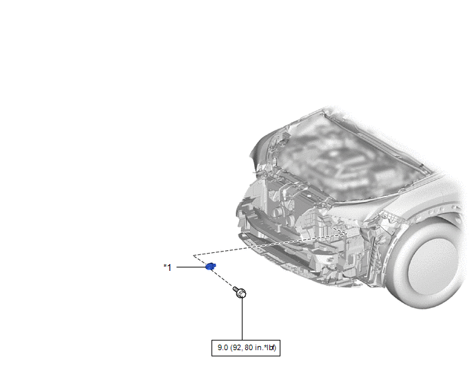
| *1 | FRONT AIRBAG SENSOR LH | - | - |
| | N*m (kgf*cm, ft.*lbf): Specified torque | - | - |
READ NEXT:
 On-vehicle Inspection
ON-VEHICLE INSPECTION CAUTION / NOTICE / HINT CAUTION: Be sure to follow the correct removal and installation procedures of the front airbag sensors. PROCEDURE 1. INSPECT FRONT AIRBAG SENSOR (for Vehi
Removal
REMOVAL CAUTION / NOTICE / HINT HINT:
Use the same procedure for the RH and LH sides.
The procedure listed below is for the LH side.
PROCEDURE 1. REMOVE NO. 3 DECK BOARD SUB-ASSEMBLY Click her
Installation
INSTALLATION CAUTION / NOTICE / HINT HINT:
Use the same procedure for the RH and LH sides.
The procedure listed below is for the LH side.
PROCEDURE 1. INSTALL FRONT AIRBAG SENSOR LH (a) Check
SEE MORE:
System Description
SYSTEM DESCRIPTION NAVIGATION SYSTEM OUTLINE (a) Vehicle position tracking methods It is essential that the navigation system correctly tracks the current vehicle position and displays it on the map. There are 2 methods to track the current vehicle position: autonomous (dead reckoning) and GPS* (sat
Disassembly
DISASSEMBLY PROCEDURE 1. REMOVE BACK DOOR UPPER OUTSIDE GARNISH LH (a) Remove the screw and back door upper outside garnish LH. 2. REMOVE BACK DOOR UPPER OUTSIDE GARNISH RH HINT: Use the same procedure described for the LH side. 3. REMOVE BACK DOOR NO. 1 GARNISH RETAINER (a) Remove
© 2016-2026 Copyright www.lexunx.com
