Lexus NX: Components
COMPONENTS
ILLUSTRATION
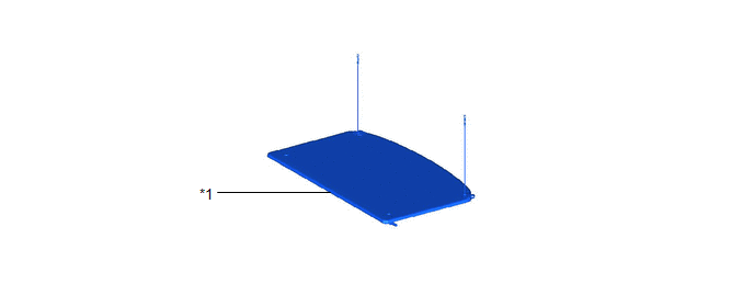
| *1 | TONNEAU COVER ASSEMBLY | - | - |
ILLUSTRATION
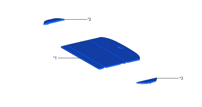
| *1 | DECK BOARD ASSEMBLY | *2 | NO. 2 DECK BOARD SUB-ASSEMBLY |
| *3 | NO. 3 DECK BOARD SUB-ASSEMBLY | - | - |
ILLUSTRATION
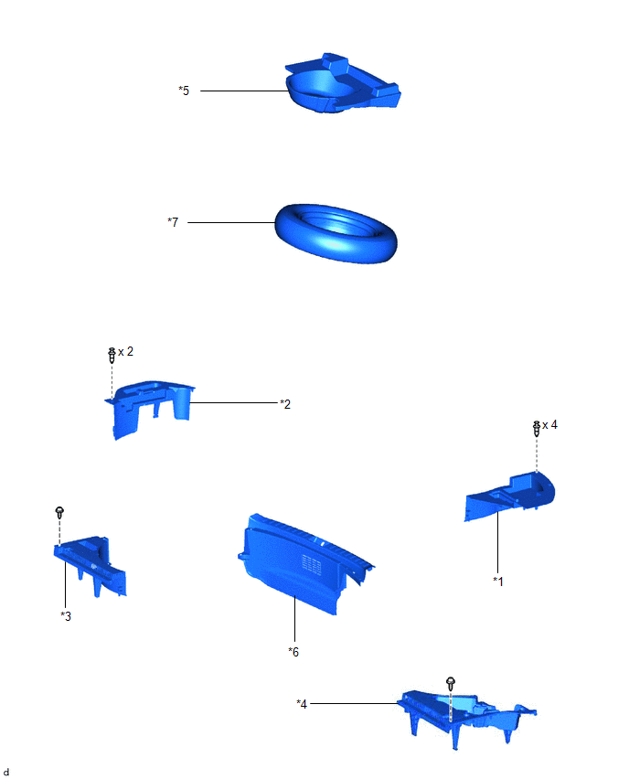
| *1 | DECK FLOOR BOX LH | *2 | DECK FLOOR BOX RH |
| *3 | NO. 1 TOOL BOX SUB-ASSEMBLY | *4 | NO. 2 TOOL BOX SUB-ASSEMBLY |
| *5 | REAR DECK FLOOR BOX | *6 | REAR FLOOR FINISH PLATE |
| *7 | SPARE TIRE | - | - |
ILLUSTRATION
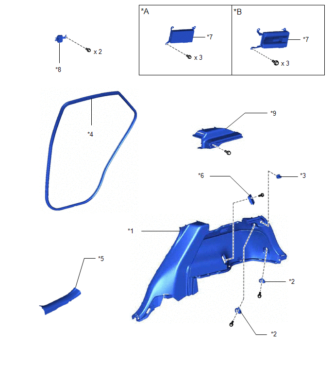
| *A | for 10 Speakers | *B | for 14 Speakers |
| *1 | DECK TRIM SIDE PANEL ASSEMBLY RH | *2 | LUGGAGE HOLD BELT STRIKER ASSEMBLY |
| *3 | NO. 1 LUGGAGE COMPARTMENT TRIM HOOK | *4 | REAR DOOR OPENING TRIM WEATHERSTRIP RH |
| *5 | REAR DOOR SCUFF PLATE RH | *6 | ROPE HOOK ASSEMBLY |
| *7 | STEREO COMPONENT AMPLIFIER ASSEMBLY WITH BRACKET | *8 | THEFT WARNING SIREN ASSEMBLY |
| *9 | UPPER DECK TRIM SIDE BOARD RH | - | - |
READ NEXT:
 Removal
REMOVAL PROCEDURE 1. REMOVE REAR SEAT ASSEMBLY (for Manual Seat) Click here 2. REMOVE REAR SEAT ASSEMBLY (for Power Seat) Click here 3. REMOVE TONNEAU COVER ASSEMBLY Click here 4. REMOVE DECK BO
Installation
INSTALLATION PROCEDURE 1. INSTALL THEFT WARNING SIREN ASSEMBLY NOTICE: Do not reuse parts if dropped or subjected to any strong impact. (a) Connect the connector. (b) Temporarily ins
SEE MORE:
Removal
REMOVAL PROCEDURE 1. DISCHARGE FUEL SYSTEM PRESSURE Click here 2. PRECAUTION NOTICE: After turning the power switch off, waiting time may be required before disconnecting the cable from the auxiliary battery negative (-) terminal. Click here 3. REMOVE NO. 3 DECK BOARD SUB-ASSEMBLY Click here 4
Precaution
PRECAUTION HANDLING PRECAUTION FOR DYNAMIC RADAR CRUISE CONTROL SYSTEM Keep in mind the following points when servicing vehicles equipped with the dynamic radar cruise control system. (a) The dynamic radar cruise control system is designed to be used when driving on highways and freeways. As the sys
© 2016-2026 Copyright www.lexunx.com
