Lexus NX: Removal
REMOVAL
PROCEDURE
1. DISCHARGE FUEL SYSTEM PRESSURE
Click here .gif)
2. PRECAUTION
NOTICE:
After turning the power switch off, waiting time may be required before disconnecting the cable from the auxiliary battery negative (-) terminal.
Click here
3. REMOVE NO. 3 DECK BOARD SUB-ASSEMBLY
Click here
4. REMOVE REAR DECK FLOOR BOX
Click here
5. REMOVE DECK FLOOR BOX LH
Click here
6. DISCONNECT CABLE FROM NEGATIVE AUXILIARY BATTERY TERMINAL
7. REMOVE THROTTLE WITH MOTOR BODY ASSEMBLY
Click here
8. REMOVE WINDSHIELD WIPER MOTOR ASSEMBLY
Click here
9. REMOVE SUSPENSION TOWER DAMPER
-
w/ Performance Damper:
Click here
-
w/o Performance Damper:
Click here
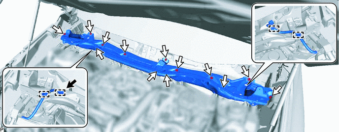
10. REMOVE OUTER COWL TOP PANEL
(a) Disconnect the connector.
(b) Detach the 4 clamps and disconnect the wire harness.
(c) Remove the 13 bolts and outer cowl top panel.
.png) | Connector | .png) | Bolt |
11. REMOVE AIR CLEANER FILTER ELEMENT SUB-ASSEMBLY
Click here
12. REMOVE AIR CLEANER CASE SUB-ASSEMBLY
Click here
13. REMOVE EGR VALVE ASSEMBLY
Click here
14. REMOVE MANIFOLD ABSOLUTE PRESSURE SENSOR
Click here
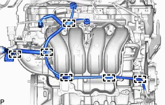
15. DISCONNECT ENGINE WIRE
| (a) Disconnect the heated oxygen sensor connector. |
|
| (b) Detach the 6 clamps and disconnect the engine wire. |
|
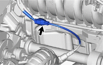
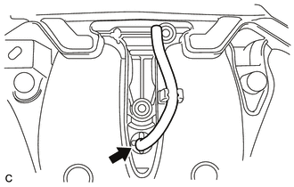
16. DISCONNECT INTAKE MANIFOLD
| (a) Slide the clamp and disconnect the No. 2 PCV hose from the intake manifold. |
|
.png)
| (b) Remove the 6 bolts and disconnect the intake manifold. |
|
.png)
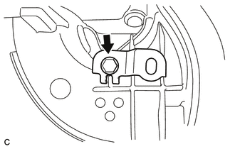
17. DISCONNECT NO. 1 EGR PIPE
| (a) Remove the nut and bolt, and then disconnect the No. 1 EGR pipe from the EGR cooler assembly. |
|
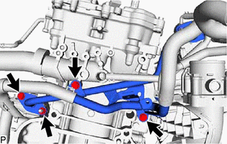
(b) Remove the 2 bolts and disconnect the No. 1 EGR pipe.
(c) Remove the gasket from the No. 1 EGR pipe.
18. DISCONNECT FUEL TUBE SUB-ASSEMBLY
Click here
19. REMOVE FUEL DELIVERY PIPE
Click here
20. REMOVE INTAKE MANIFOLD
(a) Remove the intake manifold from the vehicle.
| (b) Remove the No. 1 intake manifold to head gasket from the intake manifold. |
|
.png)
| (c) Remove the bolt and wiring harness clamp bracket. |
|
| (d) Remove the vacuum hose from the intake manifold. |
|
| (e) Slide the clamp and disconnect the purge line hose from the intake manifold. |
|
.png)
READ NEXT:
 Installation
INSTALLATION PROCEDURE 1. INSTALL INTAKE MANIFOLD (a) Connect the purge line hose to the intake manifold, and slide the clamp to secure the hose. HINT: Make sure the hose clamp is oriented as shown
Intake System
On-vehicle InspectionON-VEHICLE INSPECTION PROCEDURE 1. INSPECT INTAKE SYSTEM HINT: Perform "Inspection After Repair" after repairing air leaks in the intake system. Click here (a) Check that there
SEE MORE:
Lexus Enform Safety Connect
Safety Connect is a subscriptionbased
telematics service that uses
Global Positioning System (GPS)
data and embedded cellular technology
to provide safety and security
features to subscribers. Safety
Connect is supported by Lexus'
designated response center, which
operates 24 hours per day,
Horn Circuit
DESCRIPTION When the theft deterrent system is switched from the armed state to the alarm sounding state, the main body ECU (multiplex network body ECU) transmits a signal to cause the horn to sound at intervals of 0.4 seconds. WIRING DIAGRAM CAUTION / NOTICE / HINT NOTICE: Inspect the fuses for ci
