Lexus NX: Removal
REMOVAL
PROCEDURE
1. REMOVE REAR SEAT ASSEMBLY (for Manual Seat)
Click here .gif)
2. REMOVE REAR SEAT ASSEMBLY (for Power Seat)
Click here
3. REMOVE TONNEAU COVER ASSEMBLY
Click here
4. REMOVE DECK BOARD ASSEMBLY
Click here
5. REMOVE NO. 2 DECK BOARD SUB-ASSEMBLY
Click here
6. REMOVE NO. 3 DECK BOARD SUB-ASSEMBLY
Click here
7. REMOVE REAR DECK FLOOR BOX
Click here
8. REMOVE SPARE TIRE
Click here
9. REMOVE DECK FLOOR BOX LH
Click here
10. REMOVE DECK FLOOR BOX RH
Click here
11. REMOVE NO. 1 TOOL BOX SUB-ASSEMBLY
Click here
12. REMOVE NO. 2 TOOL BOX SUB-ASSEMBLY
Click here
13. REMOVE REAR FLOOR FINISH PLATE
Click here
14. REMOVE REAR DOOR SCUFF PLATE RH
Click here
15. REMOVE REAR DOOR OPENING TRIM WEATHERSTRIP RH
Click here
16. REMOVE UPPER DECK TRIM SIDE BOARD RH
Click here
17. REMOVE ROPE HOOK ASSEMBLY
Click here
18. REMOVE LUGGAGE HOLD BELT STRIKER ASSEMBLY
Click here
19. REMOVE NO. 1 LUGGAGE COMPARTMENT TRIM HOOK
Click here
20. REMOVE DECK TRIM SIDE PANEL ASSEMBLY RH
Click here
21. REMOVE STEREO COMPONENT AMPLIFIER ASSEMBLY WITH BRACKET
Click here
22. REMOVE THEFT WARNING SIREN ASSEMBLY
NOTICE:
Do not reuse parts if dropped or subjected to any strong impact.
| (a) Remove the 2 bolts. |
|
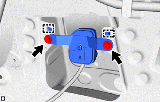
(b) Detach the 2 guides and remove the theft warning siren assembly.
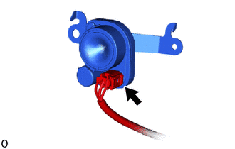
| (c) Disconnect the connector. |
|
READ NEXT:
 Installation
INSTALLATION PROCEDURE 1. INSTALL THEFT WARNING SIREN ASSEMBLY NOTICE: Do not reuse parts if dropped or subjected to any strong impact. (a) Connect the connector. (b) Temporarily ins
Precaution
PRECAUTION CAUTION REGARDING INTERFERENCE WITH ELECTRONIC DEVICES CAUTION:
People with implantable cardiac pacemakers, cardiac resynchronization therapy-pacemakers or implantable cardioverter defib
SEE MORE:
Components
COMPONENTS ILLUSTRATION *1 CLEARANCE LIGHT ASSEMBLY LH *2 CLEARANCE LIGHT ASSEMBLY RH *3 HOOD TO FRONT END PANEL SEAL *4 NO. 3 ENGINE ROOM WIRE *5 RADIATOR GRILLE SUB-ASSEMBLY *6 OUTSIDE MOULDING RETAINER ILLUSTRATION *A w/ Panoramic View Monitor System *B
A/C Inverter High Voltage Power Resource System Malfunction (B1471)
DESCRIPTION The hybrid vehicle control ECU monitors the voltage of the HV battery. The hybrid vehicle control ECU stops compressor control and stores this DTC when the monitored voltage is outside the specified range. This DTC will be stored as a history DTC. Compressor control may not resume unless
